By the way, this amp is giving all 4 signals without no MOSFETs and no 10k ohms resistor
Between pin 1 and pin 2 of U2.
Hope that helps.
Between pin 1 and pin 2 of U2.
Hope that helps.
Since you now have the scope locking, how is the signal different from the rest?
It's normal to have the same frequency as the input frequency at the FETs.
The resistor is generally necessary to see clean audio out of the TL072 to determine if it's working properly. If driven hard enough, the input signal will pass through to the FETs without the resistor.
It's normal to have the same frequency as the input frequency at the FETs.
The resistor is generally necessary to see clean audio out of the TL072 to determine if it's working properly. If driven hard enough, the input signal will pass through to the FETs without the resistor.

Good morning perry.
Can I swap the signals between shoulder to see if the getting hot problem swaps or stay in the same shoulder?
Can I swap the signals between shoulder to see if the getting hot problem swaps or stay in the same shoulder?
Last edited:
I can't determine whether the drive signals are good or not. They have to be referenced to the rails. Are the signals swinging back to within about 1v or the corresponding rails?
I'm so confuse about the signal swinging back to within about 1v or the corresponding rails.
Can you explain more explicit?
Thank you
Can you explain more explicit?
Thank you
The FETs switch on when the gate is approximately 3v higher/lower than the source leg (depending on the polarity of the FET). The source legs are tied to the rails.
The drive signal swings from the rail (or very near it) to about 10v from the rail (well over the 3v needed for it to start conducting).
When the drive signal is 'on', the gate-source voltage will be approximately 10v.
When it's 'off' the gate-source voltage must be well below the turn-on threshold. Most drive will drop the gate-source voltage to 1v or less. If the g-s voltage doesn't drop to well below the threshold voltage, it will cause the FETs to remain on and will cause them to overheat because they're fighting the other half of the FETs. If the drive voltage is too low when 'on' (3, 4, 5v...), the FETs won't turn on fully and will run hot because they're not fully on and acting as a resistor instead of a switch.
Thank you very much for explaining that.
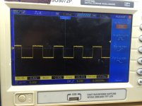
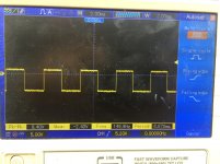
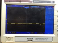
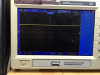
This test was done with reference to the sources. The scope shows 8.8 volts pk-pk.
Is that an Ok voltage?
By the way I test it the driver board in a working amp, and it's working Ok.
Any idea on what to check next?
This test was done with reference to the sources. The scope shows 8.8 volts pk-pk.
Is that an Ok voltage?
By the way I test it the driver board in a working amp, and it's working Ok.
Any idea on what to check next?
I'm still having trouble understanding the waveforms. It appears that the scope was set to DC coupling.
Is the scope battery powered?
If not, how did you reference to the source legs that are on the rails?
Was the scope trace aligned with the center reference line on the display when capturing the waveforms?
Is the scope battery powered?
If not, how did you reference to the source legs that are on the rails?
Was the scope trace aligned with the center reference line on the display when capturing the waveforms?
No, the scope is not battery power, it's power by 110vac.
To do this test I placed the scope ground lead on the tab of the rectifiers.
The center leg of the rectifiers are connected to the source of the mosfets.
To do this test I placed the scope ground lead on the tab of the rectifiers.
The center leg of the rectifiers are connected to the source of the mosfets.
For most scopes, the scope ground is connected to the mains ground (through the ground pin on the 3-wire power cord) and connecting any significant voltage to the ground burns the ground in the scope. It also causes the entire chassis of the scope to be at the voltage you connect the ground to. This can be lethal in some situations. To make such measurements, you need to use a differential probe setup or use a battery powered (handheld/portable) scope.
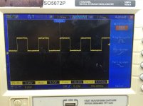
Knowing what you did still doesn't make sense looking at the images, especially for the ones that cross the reference line. The other two are what I'd expect.
Knowing what you did still doesn't make sense looking at the images, especially for the ones that cross the reference line. The other two are what I'd expect.
Hello Perry
I disconnected the power cord from my scope, and find out that the ground pin was broken inside the outlet hole. I don't have a spare cord, so I will have to wait to tomorrow for more testing, any how, I tested the signal with my voltmeter from source to gate and find out that there are three signal with voltages, two signal have 3.7 volts and one have -4 volt. the last one have 0 volts.
any suggestion?
Last edited:
Don't try connecting to the rails after you replace the cord. It's likely to damage your scope.
Re-check your measurements. If all had a signal with the scope, there's no reason that you would have 0v with the meter.
Re-check your measurements. If all had a signal with the scope, there's no reason that you would have 0v with the meter.
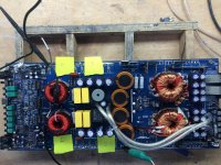
Megael9 did you replace the AG,DK transistors going to that bank of the audio mosfets that's getting hot if not try swapping them with a good channel and see if it moves to that bank
The audio driver board was test it on a working amp and audio
Was playing just fine, but know I resoldered the board back in
this amp and only three signals are present. I checked all connections
From gate pins to the driver board and they all checked ok.
Can some one tell me which are the audio input pins on the driver board?
Was playing just fine, but know I resoldered the board back in
this amp and only three signals are present. I checked all connections
From gate pins to the driver board and they all checked ok.
Can some one tell me which are the audio input pins on the driver board?
Here are the pictures of the signals with the good power cord. (With ground pin)
Attachments
Last edited:
I resolder the audio driver board pins, and now all signals are present. But the amp is still making a squeegee, Also I notice that when I test this amp without the 2 ohms
Resistor in series with the v+, the amp draws out my 35 amp power supply.
All audio mosfets are installed.
My question; what's a good resistor value to test the power supply under load?
Resistor in series with the v+, the amp draws out my 35 amp power supply.
All audio mosfets are installed.
My question; what's a good resistor value to test the power supply under load?
Test the 'power supply' under load?
If the amp is drawing excessive current at idle without the resistor, you need to determine why.
If the amp is drawing excessive current at idle without the resistor, you need to determine why.
- Status
- Not open for further replies.
- Home
- General Interest
- Car Audio
- Hifonic Hercules 4k