In a direct comparation with my last reference GM70/813 single ended amplifier this push-pull in some case give a better sound.
The bass is more fast and present.
The middle with voice are very clear.
The bass is more fast and present.
The middle with voice are very clear.
Nothing new under the sun.
Your'e gonna need global nfb for bass reflex loaded speakers with a Q higher than 1.5 and listening to classics. The article doesn't mention the damping factor value.
The unloaded low end damping will sound much too honky. The split loaded phasesplitter works excellent for a minimal component count. The only slight disadvantage is zero gain.
department of physics
richy
And i´ve heard from ppl that UL doesent sound as good as triode connected of just tieing the screen grids to the plate supply via a resistor.
Your'e gonna need global nfb for bass reflex loaded speakers with a Q higher than 1.5 and listening to classics. The article doesn't mention the damping factor value.
Did not you see feedback to cathodes from output tranny?
In a design where introducing a solid state current source to a long tailed differential pair is being looked at, why not consider the high voltage negative supply? It is easily implemented from a preexisting FW rectified positive ground referenced supply with a second bridge rectifier, pair of capacitors and a relatively small CLC or similar filter. Plus you get a fixed bias supply source for free.
I am also curious how much is really gained performance-wise by adding a solid state differential input.
I am also curious how much is really gained performance-wise by adding a solid state differential input.
Last edited:
Last edited:
Thoriated,
use a resistor in the differential with A 100v ac is impossible.
the min value to get 2 simmetric output is 220K/270k
so we need 2mA * 220K = 440V
use a resistor in the differential with A 100v ac is impossible.
the min value to get 2 simmetric output is 220K/270k
so we need 2mA * 220K = 440V
Hi -
Well, I used a long tailed diff pair cathode resistor to -500Vdc for my DC coupled OTL so that is the sole source of coloration for that portion of the circuit. I also added a small neon bulb to ground to keep the off state cathode voltage from going too far negative, but it has worked flawlessly for over 20 years.
Well, I used a long tailed diff pair cathode resistor to -500Vdc for my DC coupled OTL so that is the sole source of coloration for that portion of the circuit. I also added a small neon bulb to ground to keep the off state cathode voltage from going too far negative, but it has worked flawlessly for over 20 years.
Last edited:
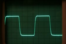
Okay lets set the stage further. Youv'e got me moving. Lets see a 10Khz 50W squarewave into a dummy load.
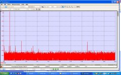
Compare your spectrum to my 120W using a concertina and Williamson diff driver.(Ignore the 15khz glitch on the spectrum)
You will get a reduced thd driving the o/p tubes harder. At 42mA this is low AB. Try 75mA per tube and see the thd fall further esp higher audio frequencies.
richy
Wavebourn: I missed this edge of pic, somehow off screen.
Attachments
sorry to say, but that PCB is horrific.
for the rest nice results, but please, consider removing the PCB or improving it a lot
for the rest nice results, but please, consider removing the PCB or improving it a lot
Richy,
75mA 400V on each EL34 ?
Try it and compare thd measurements. esp at 5Khz. Essentially one is forcing the output tubes to conduct harder, so damping the transformer LC parasitics. The result can be markedly lower thd. If one goes to KT88's or 6550 new edit, these can swallow 75mA with ease whereas the EL34 is being pushed. What margin of stability does your design have ?
I presume you are using 2K A-A primary ? Your screen resistors may be too low for pentode EL34's. The books quote around 1K. The 6550 class in UL like their screens driven hard, I often use
68R 3W new type carbon compositions.
Remember, output stage peak currents can be high as mentioned previously the cathode resistors going high resistance have caught me out. Metal film/oxide resistors have poor impulse capability.
richy
I notice there is no watchdog protection for the o/p tubes should the neg bias fail, or if a preset goes o/c. No fuse in the o/p tranny + ? In fact no fuses shown in circuit diagram.
The rms rating of capacitive input filter looks underrated for fixed bias. I wonder. What is the B+ variation from max o/p to no signal ? With low global feedback, any out of balance in the o/p stage, the 2F (mains frequency) would be noticeable in the speakers.
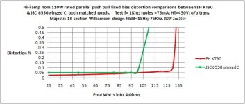
For interest, in the pic is a comparison between new version EH KT90 and JSC 6550C. In the derrated amp, with the relatively low B+ of 450V, the EH KT90 shows higher efficiency and 130W is attainable from a parallel p-p quad.
Notice the higher 75mA per tube quiescent.
richy
The rms rating of capacitive input filter looks underrated for fixed bias. I wonder. What is the B+ variation from max o/p to no signal ? With low global feedback, any out of balance in the o/p stage, the 2F (mains frequency) would be noticeable in the speakers.
For interest, in the pic is a comparison between new version EH KT90 and JSC 6550C. In the derrated amp, with the relatively low B+ of 450V, the EH KT90 shows higher efficiency and 130W is attainable from a parallel p-p quad.
Notice the higher 75mA per tube quiescent.
richy
Attachments
In a direct comparation with my 2 stage 845 amplifier on many sound tracks this push-pull amplifier give a better sound.
The single ended is the winner only in sound tracks with very few instruments like the piano solo.
The female voice is more clear on the push-pull and the bass frequency are finally present on my Onken system.
This push-pull is very different from my old PP KT88 that I don't like.
The single ended is the winner only in sound tracks with very few instruments like the piano solo.
The female voice is more clear on the push-pull and the bass frequency are finally present on my Onken system.
This push-pull is very different from my old PP KT88 that I don't like.
This push-pull is very different from my old PP KT88 that I don't like.
The art is finding out what makes it sound different ! Engineering begins here.
richy
- Status
- Not open for further replies.
- Home
- Amplifiers
- Tubes / Valves
- Hi-End 50W Push-Amplifier inspired to AudioResearch