Hi Diy'ers,
I've been doing some measurements with my oscilloscope on the PSU rails going to a DAC I'm currently working on (DSD-1794 from TI).
And it's actually been quite a surprise to see that the digital noise on the supply rails is significant (many millivolts) - even if I seem to have been just reasonably fortunate with my decoupling capacitor arrangements. And also to learn that the "altogether" PSRR of the DSD1794 is relatively limited so that these noises show up at the outputs of the DSD1794.
I am intrigued to look further into this and would like to find - or build - a simple add-on amplifier to my oscilloscope that goes from e.g 20 kHz to around 300 MHz.
I'm guessing that a total amplification of ~ 200 will allow me to look sufficiently into the noise (the oscilloscope's 2 mV resolution limit/200 = 10 uV). This should be somewhat adjustable though so I've thought of e.g. two stages of x15 amplification or a suitable variable amplification solution.
My intention is to look mainly at waveforms and frequencies so I reckon that a design without very low distortion is acceptable.
I would appreciate if one of you have suggestions for an already made (and not too expensive) amplifier - or maybe a schematic/link to a schematic that is suitable in this context? If I am to build it myself I would prefer it to a simple & small design based on maybe one or two 9 volt batteries so that I don't have to have more AC wires running.
I have considered a stage built around TI's LMH6629:
http://www.ti.com/lit/ds/snosb18g/snosb18g.pdf
... but maybe there's a better solution?
Also, I have a couple of oscilloscope probes (40 MHz Cat II, & 60 MHz Cat I), yet measuring at these frequencies I may need something better/different or more widebanded ... are there any oscilloscope probes that are better suited to this purpose, maybe considered "good", not too expensive and maybe can be had second-hand?
Thanks for reading and possibly replying 😉
Jesper
Keep the ground of the probe close to what you are probing.
I've seen noise "measured" because of the large area loop that the probe/ground path creates.
In some cases there was no significant noise at the measurement point...just loop pickup.
As a test, probe the same point the ground connection is on.
Have fun.
🙂
I've seen noise "measured" because of the large area loop that the probe/ground path creates.
In some cases there was no significant noise at the measurement point...just loop pickup.
As a test, probe the same point the ground connection is on.
Have fun.
🙂
Hey DUG,
Thanks for answering and pointing out the loop that the ground probe path may cause. However, I already use the clip-on ground "spring" that comes with the probes I have so the effective length of the ground probe is about 9 mm. Also when I change the sampling frequency of the DAC signal the noise changes frequency and level so maybe there actually is digital noise here?
But I'd actually like to get around such issues in measuring digital noise so if you or someone else here knows how to do this with the amplifier circuit I'm looking for then that would be very interesting to me.
Greetings,
Jesper
Hey DUG,
... Also when I change the sampling frequency of the DAC signal the noise changes frequency and level so maybe there actually is digital noise here?
...
Greetings,
Jesper
If changing the sampling frequency changes the results then you need to go higher (faster) sweep times.
Look up aliasing.
Later
Hi DUG,
The measurement frequencies & levels are changed on the supply rails to the DAC and to my knowledge this is plausible given that the frame sync, Master clock, data signal & bit clock changes frequencies. E.g. the bit clock goes from about 2.8 Mhz (44.1 kHz 32 bits) to 12.28 MHz (192 kHz 32 bits) when going from 44.1 kHz to 192 kHz sampling frequencies and I would expect this to change the noises present on the PSU rails (different timing of the current loads on the PSU rails).
But you are thinking something else?
Greetings,
Jesper
Look up aliasing.
The measurement frequencies & levels are changed on the supply rails to the DAC and to my knowledge this is plausible given that the frame sync, Master clock, data signal & bit clock changes frequencies. E.g. the bit clock goes from about 2.8 Mhz (44.1 kHz 32 bits) to 12.28 MHz (192 kHz 32 bits) when going from 44.1 kHz to 192 kHz sampling frequencies and I would expect this to change the noises present on the PSU rails (different timing of the current loads on the PSU rails).
But you are thinking something else?
Greetings,
Jesper
I was thinking something else...If you sample a waveform too slow, you won't be getting all of it.
I forgot about the DAC operating changes.
🙂
I forgot about the DAC operating changes.
🙂
Try this. If you connect the probe tip to the probe ground lead you should see nothing, just a perfect fine trace. Keeping those shorted, now touch the ground lead onto the ground point you have been using. Do you now see noise even though the tip is still connected to the ground lead ?
Hi Mooly,
Didn't see your reply until now ... I have tried what you suggest and when connecting the ground probe to the ground "sense" pin there's no signal on the scope. The same happens when I place the ground pin and the "sense" pin on the ground I measured on previously.
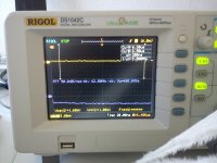
On the other hand when I place the "sense" pin on the Vcc of the DAC and the ground pin on the ground the signal looks like the attached image. Which could be better but is also "ok" as I'm learning something from it ...
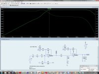
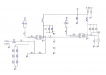
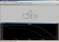
However, I'd like to do better in the future so (with some help from the LTspice forum) have experimented with the attached circuitry for the last couple of days. Its bandwidth goes from 10 kHz to appr. 160 MHz and according to the simulation there's no ringing on 10ns rise pulses (100 MHz). I intend to mount it so that the pins from the first LMH6629 to the measure circuit points are as short as possible (to reduce inductance). Amplification is 40 dBs which means that one div. resolution on my scope will correspond to ~ 20 uV.
I don't know if this is the best design possible for this purpose but it works and I reckon it can show even low noise levels on the DACs PSU rails. As a "need to know" but also out of interest 😉
Greetings,
Jesper
P.S.: I haven't added a couple of reverse diodes to the input of the first LMH6629 yet (spike over-voltage protection). The 3 nH values in the circuitry are estimates for track inductances.
Didn't see your reply until now ... I have tried what you suggest and when connecting the ground probe to the ground "sense" pin there's no signal on the scope. The same happens when I place the ground pin and the "sense" pin on the ground I measured on previously.
On the other hand when I place the "sense" pin on the Vcc of the DAC and the ground pin on the ground the signal looks like the attached image. Which could be better but is also "ok" as I'm learning something from it ...
However, I'd like to do better in the future so (with some help from the LTspice forum) have experimented with the attached circuitry for the last couple of days. Its bandwidth goes from 10 kHz to appr. 160 MHz and according to the simulation there's no ringing on 10ns rise pulses (100 MHz). I intend to mount it so that the pins from the first LMH6629 to the measure circuit points are as short as possible (to reduce inductance). Amplification is 40 dBs which means that one div. resolution on my scope will correspond to ~ 20 uV.
I don't know if this is the best design possible for this purpose but it works and I reckon it can show even low noise levels on the DACs PSU rails. As a "need to know" but also out of interest 😉
Greetings,
Jesper
P.S.: I haven't added a couple of reverse diodes to the input of the first LMH6629 yet (spike over-voltage protection). The 3 nH values in the circuitry are estimates for track inductances.
Attachments
Last edited:
Layout and construction will be everything at those frequencies, and 40db gain too... its a tall order. Not to say its not do-able though 🙂
why not get a good s/h tek analog scope for $100 ??
Digital sampling is the wrong tool for noise problems, unless you really know what you are doing. 😉
Digital sampling is the wrong tool for noise problems, unless you really know what you are doing. 😉
...
Digital sampling is the wrong tool for noise problems, unless you really know what you are doing. 😉
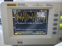
Yes, the first scope pix in post #8 looks like a one bit noise level.
It might not really be there at all.
@cliffforrest:
Hi - thanks for suggesting ... Would you happen to have a specific suggestion for an/a few oscilloscopes that fits into this category? Preferably without a blower, minimum 100 MHz bandwidth, 2 channels and s/h function ...
My reason for preferring to design a probe is that I haven't found any scopes that has a 20 uV/div vertical resolution. The probe solution would also allow me to have only scope which is much preferred.
@Mooly ... Oooohhh, have been looking into HF PCB layout & design for some time now - time to test what has been learned & hope it works out
@DUG:
Some kind on non-signal related noise would be my guess as well ... It's what the scope displays when ground and input pin is shorted so is well - just there.
Best wishes to you all,
Jesper
why not get a good s/h tek analog scope for $100 ??
Digital sampling is the wrong tool for noise problems, unless you really know what you are doing.
Hi - thanks for suggesting ... Would you happen to have a specific suggestion for an/a few oscilloscopes that fits into this category? Preferably without a blower, minimum 100 MHz bandwidth, 2 channels and s/h function ...
My reason for preferring to design a probe is that I haven't found any scopes that has a 20 uV/div vertical resolution. The probe solution would also allow me to have only scope which is much preferred.
@Mooly ... Oooohhh, have been looking into HF PCB layout & design for some time now - time to test what has been learned & hope it works out
@DUG:
Yes, the first scope pix in post #8 looks like a one bit noise level.
Some kind on non-signal related noise would be my guess as well ... It's what the scope displays when ground and input pin is shorted so is well - just there.
Best wishes to you all,
Jesper
I wonder about the practicalities of all this. Noise at those levels is almost certainly not a "real" issue anyway and the building and testing (because you would need to know that whatever results you observed were real and accurate) of such a high gain wideband amp is problematic. You are almost into RF aerial amp design territory here, now there's a thought, modifying a masthead amp 😀
"My reason for preferring to design a probe is that I haven't found any scopes that has a 20 uV/div vertical resolution. The probe solution would also allow me to have only scope which is much preferred."
That is an impossible requirement unless you have megabucks to spend!
A TEK 7000 with differential and normal plug-ins will get you the sensitivity and bandwidth - but NOT at the same time!
I use an early TEK 5000 series with a 5A22N plug-in which is brilliant for a very low noise - 20uV base - but the whole scope only has a 2Mhz bandwidth. I find this brilliant for audio. I bought this setup for about $150.
If ever I need some bandwidth I use a "portable" 2 channel TEK 475. THE basic "cooking" 'scope.
The 475 would be good. A 2465 would be better but cost more.
Analog scopes don't have s/h, by definition.
Analog scopes don't have s/h, by definition.
Hi all,
@Mooly:
😛 ... Well now, I don't exactly know what a masthead amp is but I see before me something like the antennas transmitting mobile phone signals ... I am simply not sure I can make my DAC big enough to enable hand-held measurements with such an amplifier 😉
@cliffforrest & gootee: Thank you both for your suggestions and comments. I really need the s/h functionality so if analog scopes don't have an s/h function it won't be of use to me ... But I remember seeing some kind of "hold" functionality on an analog scope earlier - or am I mistaken in this?
About the HF amplifier board - I've worked a bit further on this and have attached some images of the "final" schematic and the board layout. The board layout is a double-sided layout where the bottom layer is ground and the top is signal. I am also considering "pouring" the top layer with ground where there are no traces, but am a bit unsure about this - TI doesn't do so on their evaluation board for the LMH6629.
One of you know about what is preferred here given > 100 MHz bandwidth?
Also, if you have insights on how to optimize the board I'd appreciate hearing about this. I have BTW chosen to not have a ground area below the feedback resistors (R1 & R13) so as to reduce any capacitive coupling here.
Measurements on the DAC will be done with two pins going from the two pads to the very left of the board. Board size is ~33 mm * 62 mm. The board will be powered from 3* NiMH batteries in a case whereon the board is mounted.
Evening greetings,
Jesper
P.S.: The attached picture is of TI's evaluation board.
@Mooly:
now there's a thought, modifying a masthead amp
😛 ... Well now, I don't exactly know what a masthead amp is but I see before me something like the antennas transmitting mobile phone signals ... I am simply not sure I can make my DAC big enough to enable hand-held measurements with such an amplifier 😉
@cliffforrest & gootee: Thank you both for your suggestions and comments. I really need the s/h functionality so if analog scopes don't have an s/h function it won't be of use to me ... But I remember seeing some kind of "hold" functionality on an analog scope earlier - or am I mistaken in this?
About the HF amplifier board - I've worked a bit further on this and have attached some images of the "final" schematic and the board layout. The board layout is a double-sided layout where the bottom layer is ground and the top is signal. I am also considering "pouring" the top layer with ground where there are no traces, but am a bit unsure about this - TI doesn't do so on their evaluation board for the LMH6629.
One of you know about what is preferred here given > 100 MHz bandwidth?
Also, if you have insights on how to optimize the board I'd appreciate hearing about this. I have BTW chosen to not have a ground area below the feedback resistors (R1 & R13) so as to reduce any capacitive coupling here.
Measurements on the DAC will be done with two pins going from the two pads to the very left of the board. Board size is ~33 mm * 62 mm. The board will be powered from 3* NiMH batteries in a case whereon the board is mounted.
Evening greetings,
Jesper
P.S.: The attached picture is of TI's evaluation board.
Attachments

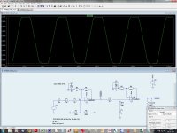
Why the low pass filter between the amplifiers?
DC gain = 1
above about 10KHz gain is 0.5
Is this to compensate for one of the high pass filters on the input and feedback of the first amp?
DC gain = 1
above about 10KHz gain is 0.5
Is this to compensate for one of the high pass filters on the input and feedback of the first amp?
Hi DUG,
My reasons for adding the 2*R & capacitor are two:
First the DC level on the output of IC1 is about VCC/2 so unless I add a capacitor I'll run about 25 mA through each of the resistors - not to mention that this will also create a voltage divider that causes the input DC level to IC2 to be appr. 1.25 volts.
Second, TI's datasheet shows the measurements for the IC at 100 ohms output loading and by making it in this way IC1 is loaded with 100 ohms. I just assume this is a sensible value since TI specifies it at this loading.
At the same time IC2's input "sees" a 25 ohms resistance (2*50 ohms parallel) which is the minimum acceptable to the Vin+ input on the LMH6629 according to the datasheet.
Best regards,
Jesper
P.S.: I've included the 50 ohm + 1uF capacitor to ground as a sort of safety precaution in case it's needed. If the circuitry just works with the 50 ohm in series between the two IC's I'll just not mount the other 50 ohm resistor and capacitor.
Why the low pass filter between the amplifiers?
My reasons for adding the 2*R & capacitor are two:
First the DC level on the output of IC1 is about VCC/2 so unless I add a capacitor I'll run about 25 mA through each of the resistors - not to mention that this will also create a voltage divider that causes the input DC level to IC2 to be appr. 1.25 volts.
Second, TI's datasheet shows the measurements for the IC at 100 ohms output loading and by making it in this way IC1 is loaded with 100 ohms. I just assume this is a sensible value since TI specifies it at this loading.
At the same time IC2's input "sees" a 25 ohms resistance (2*50 ohms parallel) which is the minimum acceptable to the Vin+ input on the LMH6629 according to the datasheet.
Best regards,
Jesper
P.S.: I've included the 50 ohm + 1uF capacitor to ground as a sort of safety precaution in case it's needed. If the circuitry just works with the 50 ohm in series between the two IC's I'll just not mount the other 50 ohm resistor and capacitor.
Last edited:
This may be of interest.
See figure 3.
RF and IF amplifiers with op amps
http://www.ti.com/lit/an/slyt102/slyt102.pdf
See figure 3.
RF and IF amplifiers with op amps
http://www.ti.com/lit/an/slyt102/slyt102.pdf
- Status
- Not open for further replies.
- Home
- Design & Build
- Equipment & Tools
- HF add-on amplifier to my oscilloscope + probes