Was thinking to move to Hexfets as Laterals are quite expensive when building a 10 pair mosfet amp. What I realized with hexfet is that they require considerable bias before they sound decent. Laterals are relatively better sounding even with little bias. I agree that NFB will alter the sound and what if no global feedback is used or very little nfb is used?
DO use NFB.
Even better, instead of "modding", build a circuit which is straight designed for Hexfets so will have taken everything in consideration.
Even better, instead of "modding", build a circuit which is straight designed for Hexfets so will have taken everything in consideration.
With HexFETs you need to pay attention to the extremely non-linear G-D capacitance. Laterals are much more forgiving. Also matching matters more because of the strong negative coefficient of gate threshold voltage with temperature.
First question is how FET OPS are coupled to VAS output. If you had to drive LatFET's gates directly from VAS output than your VAS are designed to work with something an order of ~200 pF of +-stable OPS input capacitance per FET pair. The main capacitances to drive is small reverse transfer capacitance (but driven to a high voltage difference from rail to rail) and higher but stable input capacitance (but driven from 1 to ~10-12 Volts depending of load resistance and OPS pairs.)so how different is VAS for Hexfet OPS?
If your VAS coupled with FETs through additional follower - then VAS designed to work with ~10-20 pF of stable capacitance and all FET's input capacitance are driven by that follower.
Now HexFETs.
The main difference here are a highly variable input capacitance, which in case are mainly reverse transfer and output capacitance from datasheet.
Now let's open datasheet for FQA36P15.
An order higher input capacitance when your amp's output are driven to -10 Volts from supply rails.
So, differences will be the next:
1. Directly coupled to HexFET VAS must be an order more robust compared with LatFET.
2. VAS output resistanse in case of HexFETs (for keeping worst case load frequency response) must be an order lower than LatFET.
3. As designer you must take much more precautions for cope with OPS at clipping conditions.
All other things are better to discuss having some basic amp topology or schematic.


"building a 10 pair mosfet amp" - Can you imagine the process of selecting identical mosfets and how many extra ones do you need?
Please post the schematic you are thinking about.building a 10 pair mosfet amp
As mentioned above, most designed for Laterals will have reduced drive capability, simply because those are easy and forgiving to drive so you can´t just replace one for the other and expect it to work well or at all, now some circuits might drive "anything", who knows?
Let´s see it.
As a side note, a power amp using
makes me weary and fear a horror such as those published but never ever built by anybody (not even by designer "10000W amps" which now and then pop from under the rug.10 pair mosfet
This one is "only" 1000W and I´d call it a conservative design:
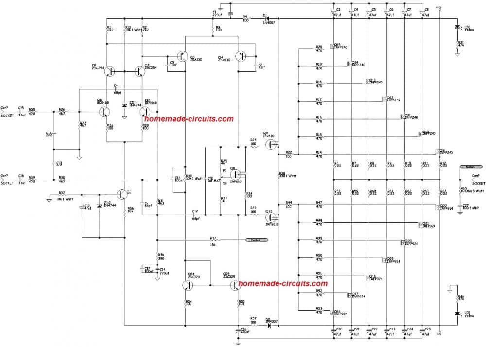
Detailed circuit and PCB: https://www.homemade-circuits.com/wp-content/uploads/2019/09/1000-watt.pdf
comments on its home page go from reasonable (from people who wouldn´t touch it with a 10 foot pole):
what about the protection circuits…like speaker on delay, dc detect, overload detect…etc
to desperate from somebody who actually believed the hype and built it:
Dear sir, please sir my audio power amplifier now shuts down light in the house, when the amplifier is powered.
It wasn’t so before.
Please sir, what could be the problem of the power amplifier?
Oh well.
Last edited:
And HEXFETs have the issue of SOA / secondary breakdown (often not given in datasheets), so you may need more of them compared to similarly rated laterals (which are only thermally limited).
When you add in the need for thermal compensation to this, the economics may not be quite so tilted toward HEXFETs as you think.
When you add in the need for thermal compensation to this, the economics may not be quite so tilted toward HEXFETs as you think.
My two cents:
Not using negative feedback is an option in class A, but not really a good idea in class AB.
10 HexFETs provide massive SOA. Dependent on the load to drive, this may be enough for 90V supply rails.
I built such a monster long time ago, which is pretty similar to the schematic posted here.
Only seven HexFETs is not enough for 92V supplies. This may have contributed to the frustration some people experienced.
The amplifier modules are not the main challenge. Everything associated is, like powering up the toroid transformers without blowing the mains fuses, protection circuitry and so on.
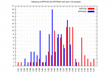
When matching HexFETs, you need to buy a lot of them. Please find attached my mileage doing so with each 100 IRFP240 and 100 IRFP9240 FETs.
Basically I would partition any amplifier into a front end (IPS), a driver stage and an output stage.
Most important is that the driver stage fits to the output stage. This can be then paired with pretty any front end.
Not using negative feedback is an option in class A, but not really a good idea in class AB.
10 HexFETs provide massive SOA. Dependent on the load to drive, this may be enough for 90V supply rails.
I built such a monster long time ago, which is pretty similar to the schematic posted here.
Only seven HexFETs is not enough for 92V supplies. This may have contributed to the frustration some people experienced.
The amplifier modules are not the main challenge. Everything associated is, like powering up the toroid transformers without blowing the mains fuses, protection circuitry and so on.
When matching HexFETs, you need to buy a lot of them. Please find attached my mileage doing so with each 100 IRFP240 and 100 IRFP9240 FETs.
Basically I would partition any amplifier into a front end (IPS), a driver stage and an output stage.
Most important is that the driver stage fits to the output stage. This can be then paired with pretty any front end.
Attachments
Thanks.
Your measurement distribution (if integrated) looks very very much like a Gauss bell 😎
Why am I not surprised? 😀
DIY Audio is infected by True Believers who diss Science and have NO CLUE about Statistics.
Me? ... HAPPY that Science proves itself right time and time again and is THE solid tool to explain the World.
Thanks for your actual tests and posting them.
Software Monte Carlo simulations are one of my hobbies, so naturally I took the measured data in post #9 and dropped it into a Monte Carlo simulator.
I defined a "matched pair" of N-channel MOSFETs as: two IRFP240 Nchannel MOSFETs that fall into the exact same histogram bin. The bins appear to be 0.01 volts wide, so a "matched pair" of IRFP240 MOSFETs differ by less than 0.01 volts. Why did I focus on the Nchannel MOSFETs (red histogram in post #9)? Because their distribution appears to be the uglier of the two, therefore more difficult to find pairs.
Somewhat arbitrarily, I decided I wanted eight matched pairs. 4 pairs for me
Then I fired up the Monte Carlo simulation. Pulling "N" transistors from the red distribution, how many matched pairs were found? If the number of matched pairs was 8 or more, that is defined as Success. If the number of matched pairs was less than 8, that is defined as Failure. Here's what the simulator says:
How to interpret the table: look near the bottom of the table where 25 transistors were pulled from the red distribution. That line tells you
That was fun. But that is all the Monte Carlo fun I want for a while. No more for me thank you, not for a while.
I defined a "matched pair" of N-channel MOSFETs as: two IRFP240 Nchannel MOSFETs that fall into the exact same histogram bin. The bins appear to be 0.01 volts wide, so a "matched pair" of IRFP240 MOSFETs differ by less than 0.01 volts. Why did I focus on the Nchannel MOSFETs (red histogram in post #9)? Because their distribution appears to be the uglier of the two, therefore more difficult to find pairs.
Somewhat arbitrarily, I decided I wanted eight matched pairs. 4 pairs for me
- 1 pair for my left channel
- 1 pair for my right channel
- 2 pairs for spares in case something goes wrong
Then I fired up the Monte Carlo simulation. Pulling "N" transistors from the red distribution, how many matched pairs were found? If the number of matched pairs was 8 or more, that is defined as Success. If the number of matched pairs was less than 8, that is defined as Failure. Here's what the simulator says:
Code:
     5000 runs  100 transistors pulled; >=8 matched pairs  100.00 pct (5000 / 5000)
     5000 runs   95 transistors pulled; >=8 matched pairs  100.00 pct (5000 / 5000)
     5000 runs   90 transistors pulled; >=8 matched pairs  100.00 pct (5000 / 5000)
     5000 runs   85 transistors pulled; >=8 matched pairs  100.00 pct (5000 / 5000)
     5000 runs   80 transistors pulled; >=8 matched pairs  100.00 pct (5000 / 5000)
     5000 runs   75 transistors pulled; >=8 matched pairs  100.00 pct (5000 / 5000)
     5000 runs   70 transistors pulled; >=8 matched pairs  100.00 pct (5000 / 5000)
     5000 runs   65 transistors pulled; >=8 matched pairs  100.00 pct (5000 / 5000)
     5000 runs   60 transistors pulled; >=8 matched pairs  100.00 pct (5000 / 5000)
     5000 runs   55 transistors pulled; >=8 matched pairs  100.00 pct (5000 / 5000)
     5000 runs   50 transistors pulled; >=8 matched pairs  100.00 pct (5000 / 5000)
     5000 runs   45 transistors pulled; >=8 matched pairs  100.00 pct (5000 / 5000)
     5000 runs   40 transistors pulled; >=8 matched pairs  100.00 pct (5000 / 5000)
     5000 runs   35 transistors pulled; >=8 matched pairs  100.00 pct (5000 / 5000)
     5000 runs   30 transistors pulled; >=8 matched pairs   98.84 pct (4942 / 5000)
     5000 runs   25 transistors pulled; >=8 matched pairs   68.00 pct (3400 / 5000)
     5000 runs   20 transistors pulled; >=8 matched pairs    4.38 pct ( 219 / 5000)
     5000 runs   15 transistors pulled; >=8 matched pairs    0.00 pct (   0 / 5000)
How to interpret the table: look near the bottom of the table where 25 transistors were pulled from the red distribution. That line tells you
If IRFP240's really do follow the red distribution, then:
If you grab 25 IRFP240's completely at random,
there is a 68% probability that those 25 transistors will give you 8 or more matched pairs
That was fun. But that is all the Monte Carlo fun I want for a while. No more for me thank you, not for a while.
A few comments on the amplifier circuit published by Best Electronic Circuit Projects
This reminds me of the AV800 / AV1000 amplifiers that Anthony Holton came up with decades ago. Both schematic and PCB design seem pretty similar, but Anthony's design used 10x HexFETs for 1000W, which makes much more sense.
It takes a good thermal concept to get rid of 270W idle power dissipation - per channel (assumed 150mA bias per FET).
Apart from the 7x FET output stage being incapable of 1000 Watt, the schematic has more flaws that may lead to frustration.
Lack of an output inductor almost guarantees instability with real world loads.
Compensation doesn't look promising (but may have been done this way because the stabilizing output inductor is missing).
The Vgs multiplier potentiometer connection is stupid and may result in blowing up the output stage.
Better not build this. I'm writing this to deter any inexperienced DIYers that underestimate the difficulty of building such a monster (just like me ten years ago). At least I fixed some of the pitfalls and the amp worked well, although I never had the chance to test it at high power.
The concept is not about driving Hexfet directly from the VAS. Anyway the input capacitance of the Hexfet will be quite high resulting higher distortion. The question is that if a simple BJT is used take Ksa1381 and Ksc3503 to drive 3 pairs of Hexfets in the OPS. But is there any consideration when you have Hexfet in output. My observation of hexfet is that you need alot of bias to make them sound reasonable and Laterals sounded much better even with medium bias.
The only concern that I had is that is there anything in the output of the VAS to be considered to drive the Hexfets based OPS with any BJT driver or take mosfet drivers like FQP3N30 FQP3P30
The only concern that I had is that is there anything in the output of the VAS to be considered to drive the Hexfets based OPS with any BJT driver or take mosfet drivers like FQP3N30 FQP3P30
- Home
- Amplifiers
- Solid State
- Hexfets Vs Laterals when IPS being same.