That's not the numbering for the 1260 but at least I can see what you have.
Do you have a good square wave from the two outputs of the driver IC, IC1?
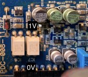
Post the same type of photo for the voltage on Q6 and Q7.
Do you have a good square wave from the two outputs of the driver IC, IC1?
Post the same type of photo for the voltage on Q6 and Q7.


That's better. There are two dimples. The angled side is the 1-2 side.
Is R25 being pulled to ground on the terminal that's not connected to Q7?
Is R25 being pulled to ground on the terminal that's not connected to Q7?
Thanks, now the pins for optocouplers are clear.
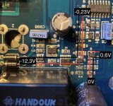
When I measure DC voltage on R25 (black probe on amps GND terminal, red on resistor), on the side going to IC3 board there is 0V. When I measure DC voltage on resistors side which is connected to Q7 the relay clicks and I read -12V.
When I measure DC voltage on R25 (black probe on amps GND terminal, red on resistor), on the side going to IC3 board there is 0V. When I measure DC voltage on resistors side which is connected to Q7 the relay clicks and I read -12V.
Meter at 200kOhm setting showed open circuit while probes pressed to either end of the resistor. Soldered it out to be sure because it was covered in glue, while out of circuit even meter at 2MOhm setting still reads open circuit.
I have very little stock of parts left from when I was more into amps, what do you think, 33k resistor is ok for testing?
- Home
- General Interest
- Car Audio
- Hertz EP1D