For the DDDAC, you need Bitclock (BCK), Left Right Clock (LRC) and DATA. And Ground.
With your DDDAC mainboard, you should have received a short female/female ribbon with 10 pins headers.
On the Cronus, I use the "B3" header, with male headers pointing UNDER the Cronus board.
Only the 3 used signals on one side, and the 5 ground pins on the other (check the first attachment)
This way, you can connect the ribbon like on the second attachment.
I hope it's not too obscure 😀
Perfect! I'll work with this ... 🙂
By the way, what do you mean with those questions:
Cronus is synchronous in its principles...
It is the clock master, feeding a slave source, reclocking on the same master clock then feeding a slave DAC (which DDDAC is).
Not sure what you were asking here 😕
No, me neither (not knowing what I'm asking), but I have seen 'discussions' on whether to go with synchronous or asynchronous connections from Cronus to dac. But I'm happy with your answer, and will try to get it to work as you explained it 🙂
Ah ok, those discussions were about ESS dacs like the TPA Buffalos.No, me neither (not knowing what I'm asking), but I have seen 'discussions' on whether to go with synchronous or asynchronous connections from Cronus to dac. But I'm happy with your answer, and will try to get it to work as you explained it 🙂
(which can use async reclocking with its own clock, or just sync).
The DDDAC is a pure slave dac.
Feel free to ask when you'll be at it (except about BBB which I don't have...) 😀
For the DDDAC, you need Bitclock (BCK), Left Right Clock (LRC) and DATA. And Ground.
With your DDDAC mainboard, you should have received a short female/female ribbon with 10 pins headers.
On the Cronus, I use the "B3" header, with male headers pointing UNDER the Cronus board.
Only the 3 used signals on one side, and the 5 ground pins on the other (check the first attachment)
This way, you can connect the ribbon like on the second attachment.
I hope it's not too obscure 😀
So in this way all the pins/lines get exactly where they are supposed to go? That is fantastic! 🙂
That's it.
But beware the VDD connector on the DDDAC header.
3.3V or 5V on the wrong pin could possibly damage the Cronus.
You can even cut the pin on the DDDAC board to be safe.
But beware the VDD connector on the DDDAC header.
3.3V or 5V on the wrong pin could possibly damage the Cronus.
You can even cut the pin on the DDDAC board to be safe.
EN on = Hermes is powered on
others are "unused", you can control them if you want:
- P9_11
- P9_12
- P9_13
Also there are 3 pins available for push buttons on J_RE connector, pulled up to 3.3V::
- P9_16
- P9_15
- P9_23
others are "unused", you can control them if you want:
- P9_11
- P9_12
- P9_13
Also there are 3 pins available for push buttons on J_RE connector, pulled up to 3.3V::
- P9_16
- P9_15
- P9_23
Thank you Miero,
I am asking because on many photos I see all 4 LED on. On my Hermes LED label "2" is not working (double checked orientation and solder joints). I suspect the small IC labeled QA3 has 5,1 V in but only 0,39 V out. Where the other IC (QA1, QA2, QA4) have 5,1 V in an 5,1 V out. As I do not know what type it is I do not know if it is defect or disabled (in software)?
Does someone know replacement type?
Thank you
Branko
I do not know if it is defect or disabled (in software)?
On mine #3 doesn’t light. It is completely unrelated to questions of performance. I use EN and 1 to drive external leds - a nice convenience rather than needing a separate driver circuit if they were run by other GPIO pins. If three are working you can drive an RGB led for color-coded messages! ...and each color will be nearly equally bright, I believe. 🙂
Here are matching GPIO numbers and a link how to use them from command line...
Hermes-BBB GPIOs: LEDs & inputs
EN on = Hermes is powered on
others are "unused", you can control them if you want:
- P9_11 (gpio 30)
- P9_12 (gpio 60)
- P9_13 (gpio 31)
Also there are 3 pins available for push buttons on J_RE connector, pulled up to 3.3V::
- P9_16 (gpio 51)
- P9_15 (gpio 48)
- P9_23 (gpio 49)
How to control GPIO pins from a command line:
IO pin control from the command line – Raspberry Pi Projects
A new TPA documentation blog seems to be available! Great work Russ!
Here are documentation pages for Cronus & Hermes-BBB that will be improved: Docs
Thanks! You can now get the gerbers and the design files as well as the schematic for Hermes-BBB.
Hi,
I want to use a BBB with the hermes board for a dual mono dam1121.
Do you see an option to take the MCKL signal from one dam1121-01 (Si570) and feed it to the hermes board as master clock, wich in turn gives it further to the BBB so, everything is in sync to the dam?
I'm pretty stuck in here. I don't know how this should work, especially how to wire up so the dam will select the proper clock as its programmable XO. Or how to set the driver so the clock select signal is available to the dam
Thank you very much,
janho12345, yes check the Hermes-BBB schematics [1]
You need to feed MCLK signal to MCK_IN pin of Hermes header.
And you attach clock selector on dam1121 to CS pin.
Pins on Hermes header of Hermes-BBB:
[1] (out) BCLK ... bit clock
legend: {PCM_MODE}/{DSD_MODE}
[3] (out) LRCK/D0 ... word clock or DSD data
[5] (out) D0/D1 ... data for stereo DAC or multi-channel PCM
[7] (out) D1/CLEAN_GND ... data for multi-channel PCM or "smart stereo wiring" for multichannel Buffalo 3
[9] (out) D2/CLEAN_GND ... data for multi-channel PCM or "smart stereo wiring" for multichannel Buffalo 3
[11] (out) D3/D2 ... data for multi-channel PCM or with [5] for dual-mono emulated using multichannel playback (no FIFO needed)
[13] (out) CLEAN_GND/D3 ... data for multi-channel PCM or "smart stereo wiring" for multichannel Buffalo 3
[15] (out) CS ... clock selector ... output level can be inverted in "ext_masterclk" of Botic driver
[17] (in) MCLK
[19,20] (in) 3.3V ... voltage for clean side of Hermes-BBB isolators
[others] CLEAN_GND
The "dual-mono emulated using multichannel" requires a setting serconfig of Botic driver to "IDDI". And some alsarc magic to play on 4 channels.
[1] Hermes-BBB/hermes-bbb-schematic.pdf at master * twistedpearaudio/Hermes-BBB * GitHub
Last edited:
Thanks!,
But, there’s a little problem concerning CS. It’s not enabled in Dam1121, as far as I know.
Another problem is the CLK in of the dam 1121, this is a LVDS not hcmos.
So, I’m thinking of using Cronus’ MCKL out.
Are the new buffered MCKL out of the Cronus in CMOS?
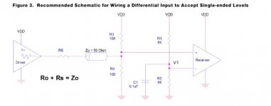
If so, could I use the connection scheme from diagram below or should I even drive a translator?
Thank you very much!
But, there’s a little problem concerning CS. It’s not enabled in Dam1121, as far as I know.
Another problem is the CLK in of the dam 1121, this is a LVDS not hcmos.
So, I’m thinking of using Cronus’ MCKL out.
Are the new buffered MCKL out of the Cronus in CMOS?
If so, could I use the connection scheme from diagram below or should I even drive a translator?
Thank you very much!
Attachments
I guess you need to use Hermes-BBB + Cronus (with clocks) + Dam1121. You cannot use clocks from dam, because you are not able to control its frequency, and also its manual states it is very sensitive.
If you do not need 44.1k rates, then you could omit Cronus and use just internal 48k clock on the BBB (snd_soc_botic.ext_masterclk=0).
If you do not need 44.1k rates, then you could omit Cronus and use just internal 48k clock on the BBB (snd_soc_botic.ext_masterclk=0).
thank you!
I know it’s a Hermes thread here but,
In a Setup where Cronus is a clock master, dam and BBB are slaves,
do you know what type of output the MCKL of the Cronus as Clock master (with two clocks) is? Because the Dam wants LVDS signal, that’s why I’m asking if the above posted scheme for a simple CMOS to LVDS translation is possible or if I should get a translator/buffer like this one : https://www.idt.com/document/dst/8p34s2102-datasheet
Thank you Miero, you’re a big help here!!!
- Home
- More Vendors...
- Twisted Pear
- Hermes-BBB/Botic cape for BeagleBone Black