slepro said:
Why should I remove these capacitors? I don't see any reason why I should remove them. The amplifier was carefully simulated with Pspice before ANY prototypes, and the results were better with there capacitors than without.
C1 and C10 has a similar purpose as C4 and C8. Why not using only C4 and C8 (redefine proper value) or C1 and C10 (redefine proper value)? Or simply use RC across your R19 and R8 to avoid miller caps (however you might need also a cap between colector of Q2 and ground. But this is your decision.
slepro said:
I know that lineup is having the same remark as you for C6 and a resistor in // with it. I put that capacitor there to have less gain at high frequency, but again, I don't see any reason of putting a resistor to allow a DC current flow. The DC current flow is made through the output transistors bases and emitters (don't forget that I drive this amp output stage in class A, so I have at least 5mA through the emitters of Q19 and Q5.
The emitter current in Q19 or Q5 is more function of the beta variation without a resistor there. Using a resistor can define a more "stable" emitter current. I do not recall seeing an audio amp without that resistor in a darlington configuration but I might be wrong. Again, this is your choice.
Also, have you finally fixed your 'noise' issue?
What is your DC offset voltage?
Fab
Thanks Fab for your comments.
This weekend I had a couple of hours to work on the amp. I tried almost all the suggestions posted here, but without good results. The shhhhhh noise is still there. The only thing that changed is the DC offsest output voltage. Before it was -0.075V and now it is at -0.250 which is not very good. I noted this variation after changing R11 and R14 to lower values.
Maybe during the holidays I will have more time to spend on the amp.
noise problem...
Hi slepro
Datasheet noise:
2N5461: 60 to 115 nv/SQRoot(Hz)
2SJ74: 0.95 nv/SQRoot(Hz) typical
Also, ensure that your pre-amp output impedance is not too high since it will increase the noise on your power amp.
Do you have scope to check the "shape" of the noise (white noise, oscillation, ...) or have you measured with a simple AC voltmeter in milivolt scale with shorted input.
For DC offset this is what I suspected since you have neither a DC servo nor a feedback cap. In fact, your previous R14 value was correctly selected for DC offset since equal to R13. We made you change it for noise optimization only and not for DC offset. You can use a trimmer between fet input sources to correct DC if you want to or use better match jfet but it may be a though job...
Good luck
I don't really trust my scope for this kind of signal, but when probing the output of my amp, I can sync to a very high frequency (in the range of MHz) sinusoidal oscillation. The amplitude of the oscillation is about 50mV pk-pk.
But since I can hear the noise, I would guess a main frequency in the range of 12 - 15 kHz. Anyway, I'm pretty shure that the noise is coming out of the JFET transistors. Do you know how I can get the 2SJ74 and his friend 2SJ170 from Toshiba, in Canada?
Also what are you meaning when your talking about DC servo?
Tks!
50 mv MHz oscillation should be fixed in my opinion since probably easy to fix anyway ( base stoppers at output transistors?)
For jfets, see at:
http://www.borbelyaudio.com/pics/Compprice.pdf
I do not know a place in Canada that can provide matched complementary jfets. There is a minimum order but I may also need some parts so we possibly could combine an order together.
For the DC servo, it consists of an op-amp as an integrator in the feedback path. See circuit with Q9 in this example at:
http://www.borbelyaudio.com/adobe/servo50.pdf
It removes the DC component of the signal and it is done dynamically instead of statically in steady state condition.
Do you know the price for matched 2SJ109BL and J176?I do not know a place in Canada that can provide matched complementary jfets. There is a minimum order but I may also need some parts so we possibly could combine an order together.
fet
See on the Borbely link I have provided in my previous post. It explains the added price for matching as well. However, there is an exception for the 2SJ109BL that it can no be matched with corresponding complementary 2SK389BL.
Sorry, for 2SJ176 I do not know.
Ryssen said:
Do you know the price for matched 2SJ109BL and J176?
See on the Borbely link I have provided in my previous post. It explains the added price for matching as well. However, there is an exception for the 2SJ109BL that it can no be matched with corresponding complementary 2SK389BL.
Sorry, for 2SJ176 I do not know.
For those that may be interested, I will shortly publish the final version of this marvelous amplifier! Very stable, high 50kHZ BW, rise time of 2.5us at full output.
I can't wait to build better speaker to fully enjoy this amp!
I can also give the layout to any one of you that would like to have it.
😀
P.S. I did'nt realize at first, but my nick has changed since my first post, so I'm the same guy as the one that started this thread, wich is slepro.
I can't wait to build better speaker to fully enjoy this amp!
I can also give the layout to any one of you that would like to have it.
😀
P.S. I did'nt realize at first, but my nick has changed since my first post, so I'm the same guy as the one that started this thread, wich is slepro.
Hi RedFloyd,
Interesting circuit with lots of promise.
May I offer a few comments?
C5 could be reduced to 1uF. Plenty of bass will still get through, and a 1uF cap of good quality is much cheaper.
The gain of the input stage is yfs x RL, which will be lower than a bipolar LTP, so your OLG will be somewhat lower. You've picked this up with bypass degeneration on the two VASs; it might be better, though at cost of some offset stability, to use only around 22R of unbypassed degeneration on the VASs and reduce the values of R8/R19 to 1K.
This will maintain your 19mA of VAS current, which is probably a bit high actually.
I agree with Roar Malmin that the feedback resistors should be around 1K5/18K. The 560K resistor would likely be the source of your noise problem. And the largest emitter resistor I'd use on the outputs would be 0R47.
You have used 100pF of lag compensation. Give some thought to carefully setting this around 33pF, and then adding phase lead of around 15pF from the collector of Q2 back to the fb node.
This will take a lot of fiddling around, it is empirical and difficult to derive mathematically. Less lag comp is good since it has sonic benefits.
Someone here mentioned a resistor between the emitters of the drivers. An excellent suggestion, try it!!
A Zobel improves damping AND stability, enabling lower lag compensation to be used. Try it, your idea is nice but the amp will work better with a Zobel, believe it, I have tried to do it too!
A nice circuit, congratulations!
Ciao,
Hugh
Thanks to all of you for your suggestions and recommendations. Finaly, the source of my oscillations was.... heeee... I must admit a bad conception from myself. In fact, the two capacitors in // with R1 and R24 were the source. When considering the DC operating point, there was no problem, since the caps helped stabilise the current. BUT, when analysing small signal, both emitters of Q21 and Q3 were shorted to +50V and - 50V BECAUSE of those capacitors. So, when removing them, the oscillotion disapeared. So now everything is good.
In the new revision, I also included some changes in the first stage, which are:
- the addition of a HP filter at the input
- the addition of gate resistors for the JFET
- The JFETs are now 2SK170 and 2SJ74
- The possibility for drain series resistors
- Some decoupling caps here and there
- There is now a DC path between Q19 and Q5
- Smaller stability capacitors C4 and C8
The reason why I choose 1 ohms emitters resistor for the output stage is to ensure a good balance between output transistors, and it works!
So you will find attached the final version of the schematic
Enjoy!
Attachments
still no Zobel on the output.
r18 & r10 seem to be before the Vbe multiplier. I think they should be after the multiplier.
Put that C back parallel to r40.
what bias are you running the Input LTP at?
what bias are you running the VAS at?
what bias are you running the drivers at?
what bias are you running the output stage at?
r18 & r10 seem to be before the Vbe multiplier. I think they should be after the multiplier.
Put that C back parallel to r40.
what bias are you running the Input LTP at?
what bias are you running the VAS at?
what bias are you running the drivers at?
what bias are you running the output stage at?
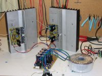
I'm using a Antek 500VA 2x30V transformer at 1A DC current operating point at the output transistor for each channel.
Full output into 10 ohms is more than 60Vp-p, so at 8 ohm this give 56W rms. The rise time and fall time is 2 us using a squre wave, 60Vp-p into the same load.
I'm very happy with these amps, the only bad thing is that my heatsink aren't big enough the dissipate all the power generated with a 2A dc operating point. So that's why I'm using it at 1A for now.
Here is a picture of my current setup.
Attachments
You seem to be very keen on running MUCH current through your zeners, yet you starve the drivers. They run at approx 3mA. At this current, they will be switching all over. What is the rationale behind this? Also, there is no need to use gate resistors on the input FETs.
Regards
Roar
Regards
Roar
AndrewT said:Does your 1A output bias = 330mVre?
Yes!
Roar Malmin said:You seem to be very keen on running MUCH current through your zeners, yet you starve the drivers. They run at approx 3mA. At this current, they will be switching all over. What is the rationale behind this? Also, there is no need to use gate resistors on the input FETs.
Regards
Roar
Where do you see MUCH current through the zeners? Look at the datasheet of the 1N5246 and you'll see that Iz is about 7.8mA. I'm running the zeners at about 8mA (considering that current is being drawn by the base of q17 and Q18).
I starve the drivers?? Did you look at the datasheet of the 2sk and 2sj?? It's better for them to run at 1mA if I want good open loop gain.
And for the Zobel... For now I'm trying without it. Maybe later I will try using one.
I would be happy to see someone build a copy of this amp!
Regards,
Sebastien
Q5 and Q19 are the drivers. They run at about 3mA with the values shown. In this configuration you can happily run them with a current of up to at least 50mA. This will give you much cleaner drive of the outputs. R40 should also be paralelled with up to 1uF of PP cap. I was referring to D1 and D4, not the LTP zeners.
Regards
Roar
Regards
Roar
That's why I asked these questions, but he is intent on ignoring the message I am trying to impart.AndrewT said:still no Zobel on the output.
..............
what bias are you running the Input LTP at?
what bias are you running the VAS at?
what bias are you running the drivers at?
what bias are you running the output stage at?
It is a sad situation when people with a white stick, refuses to be led over the road. Better use the energy where it is appreciated. Andrew, you have shown admirably self-restraint.
Regards
Roar
Regards
Roar
AndrewT said:
That's why I asked these questions, but he is intent on ignoring the message I am trying to impart.
I'm not ignoring it, but I don't like to answer questions when the answer is under your nose. Well, since you are all trying to help me, I will try to answer your questions.
- what bias are you running the Input LTP at?
Not sure what the LTP is, but the JFET are biased at 1mA each.
- what bias are you running the VAS at?
Not sure what the VAS is, but there is 20mA flowing thru Q22 and Q2
- what bias are you running the drivers at?
The drivers bias is dependent of the output stage current, and it's a function of the gain of the output transistors. So if I'm running output bias at 333mA for each output device, the drivers bias is 3mA + 3*0.333A/45. That gives about 25mA.
- what bias are you running the output stage at?
Because of heatsink limitation, the output stage bias is 0.333A for each output transistors.
About the Zobel network, what are the main advantages of it? Is it false to think that if the amp is stable enough, fast enough and is having a low output equivalent resistance, the Zobel can be eliminated?
Thanks all.
- Status
- Not open for further replies.
- Home
- Amplifiers
- Solid State
- Here is my last creation - DOCAFET class A amp!