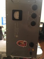
Hello Everyone! I am in the process of fixing a High Voltage Regulated Power Supply that I purchased off eBay for 200 Flat (Sold as Broken) - probably made in the early 1960s. The unit is made by the Northeast Scientific Company in Acton, Mass. Model Number RE-6506P I have serial Number 22 interestingly, I checked to see if the company was still around but sadly they are out of business as of 2017!
I was not able to find any documentation for this unit from the usual sources. More than anything I am seeking a schematic. I do not want to have to make one but if I do, I promise I will publish it for free. Tube Complement is as follows
5x - Glow Discharge 5651A
1x - Beam Power 6FW5
3x - 12AX7 Twin Triodes
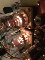
2x - EIMAC 4-125A
When I acquired the device, only one tube would light up when it was switched on Standby, I got the rest on after fixing some cold solder joints and bypassing a bad winding in the filament supply with a different transformer. I have turned on the B+ section and I am very close to have this device in working order, (I Hope)
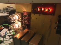
The voltage rises to 500 Volts on the output but the current meter is near the maximum of this supply (300 watts at 50ma well at 6kv) and the plates on the 4-125 begin to turn red. When I select 1000 Volts - it gets worse and the ma meter becomes pegged - the supply is in overdrive state. In addition you will note that 1 of the 5 glow discharge tube is not glowing? I have no idea if it comes on at a later point or if it part of the problem.. The tube that is out connects to one of the capacitors I had to replace.
I don't know where but somehow the voltage is being discharged or leaking probably via a faulty component. What I need most is a schematic - does anyone have any experience with power supplies produced by Northeast Scientific Company?
See pictures attached for more information ...
Any and All Information including Suggestions are Appreciated: Thank You
Keith
I was not able to find any documentation for this unit from the usual sources. More than anything I am seeking a schematic. I do not want to have to make one but if I do, I promise I will publish it for free. Tube Complement is as follows
5x - Glow Discharge 5651A
1x - Beam Power 6FW5
3x - 12AX7 Twin Triodes
2x - EIMAC 4-125A
When I acquired the device, only one tube would light up when it was switched on Standby, I got the rest on after fixing some cold solder joints and bypassing a bad winding in the filament supply with a different transformer. I have turned on the B+ section and I am very close to have this device in working order, (I Hope)
The voltage rises to 500 Volts on the output but the current meter is near the maximum of this supply (300 watts at 50ma well at 6kv) and the plates on the 4-125 begin to turn red. When I select 1000 Volts - it gets worse and the ma meter becomes pegged - the supply is in overdrive state. In addition you will note that 1 of the 5 glow discharge tube is not glowing? I have no idea if it comes on at a later point or if it part of the problem.. The tube that is out connects to one of the capacitors I had to replace.
I don't know where but somehow the voltage is being discharged or leaking probably via a faulty component. What I need most is a schematic - does anyone have any experience with power supplies produced by Northeast Scientific Company?
See pictures attached for more information ...
Any and All Information including Suggestions are Appreciated: Thank You
Keith
Attachments
No luck tracing this company , I know you said it went out of business but tried Acton MA websites ,still no luck , was this company a subsidiary of a bigger one ?
I would agree made in the 60,s although the meter looks older .
I had a UK version but couldn't put it to any great use so scrapped it for parts including some HV transmitting tubes fitted in it.
The gas discharge tubes should regulate it do you have a means of testing them ?
Leakage at very high voltages should be obvious but capacitors are the first thing I would check---for leakage .
I wouldn't leave the tubes plates running glowing red could end up with internal shorts on them.
Honestly I have traced faults through much more densely populated circuits than that one it just requires a logical sequence and -----time.
Current limiting is usually applied to VR tubes via an external resistor--check them for value as stated on them.
The 5651A is near the 85A2 tube ( in voltage regulation )
Do you really need a seven THOUSAND volt supply?
Please do not get killed.
All the gas regulator tubes should glow at idle. Glow-tubes get harder to start every decade; they used a wisp of radioactive gas to excite the starting process and it decays. Oddly eBay is full of them, though I would trust 85V of Zener today. Light will also help start them; I used to pop the back off my Boonton meter to get it to stabilize.
Do you understand the *basic* tube regulator plan?
Now the problem I have is that the voltage amplifier before the passtube (the 4-125s) needs to stand-off nearly full output voltage. However the nearest thing to a high-Volt amp tube here is the H-sweep 6FW5. Which is only good for 770V.
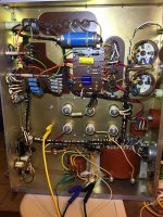
Ah-Ha. This and the HUGE board area around the sockets means the error amp is working "inverted". You see this on some chip regulators. Do not recall one in tubes but maybe Duncan knows a cite. When outputing 7,000V, the 6FW5 cathode and all the other small-stuff is at maybe 6,500V (so will kill you). Only a voltage divider runs all the way to nominal zero V.
This also suggests why you had heater winding trouble, and may again unless you found a heater transformer insulated for many thousands volts.
Please do not get killed.
All the gas regulator tubes should glow at idle. Glow-tubes get harder to start every decade; they used a wisp of radioactive gas to excite the starting process and it decays. Oddly eBay is full of them, though I would trust 85V of Zener today. Light will also help start them; I used to pop the back off my Boonton meter to get it to stabilize.
Do you understand the *basic* tube regulator plan?
Now the problem I have is that the voltage amplifier before the passtube (the 4-125s) needs to stand-off nearly full output voltage. However the nearest thing to a high-Volt amp tube here is the H-sweep 6FW5. Which is only good for 770V.
Ah-Ha. This and the HUGE board area around the sockets means the error amp is working "inverted". You see this on some chip regulators. Do not recall one in tubes but maybe Duncan knows a cite. When outputing 7,000V, the 6FW5 cathode and all the other small-stuff is at maybe 6,500V (so will kill you). Only a voltage divider runs all the way to nominal zero V.
This also suggests why you had heater winding trouble, and may again unless you found a heater transformer insulated for many thousands volts.
HV PSU
Thank You both for your input and concern for my safety. I do have a valid need for a 300 Watt 7KV Power Supply! Myself and a few good electronic professionals are toying with a number of new Ideas in Electric Propulsion. Some of our test articles will break down and short to out, I feel an older tube fired supply is more robust then a more modern HV Power Supply in terms of being over-driven and surviving a short to ground at a high voltage. (And Cheaper) This unit has a grounded case and a safety interlock function, w00t.
I need to become more acquainted with tube regulated supply design because the filament circuit does connect to other parts in the circuit. The regulator tubes did not glow, until I grounded the temporary filament transformer's center tap, to case-ground. It should be good to atleast 1000 volts but I might have to buy an identical HV PSU, without a blown filament transformer to get this working. Not something I would like to do and I am still trying to verify the operation of the high voltage side. I even tried to take it’s filament transformer apart – to see if rewinding was an option, but the windings are encased in a bakelight like material… As you suggested isolated for high voltage probably.... I will measure the voltage across the transformer and report back, the windings for the largest tubes are good. The burnt side was used to power one side of a 12ax7 heater and also connects to the regulator tubes.....
Can you identify a part for me? – If you look at the picture of the rear – on the top, there is a blue capacitor like object, my friend thinks it might be a selenium rectifier – my LCR meter says it’s an 80nf capacitor – obviously high voltage; there is no writing on the device.
I will look up the design of inverted style - regulated tube power supplies, my tube experience ends with push-pull amplifiers. Any old books or articles that you could recommend would be of value...
As far as the tubes themselves on this unit – I have replaced them all with NOS units. Everything should be functional tube wise.
You can take my word on it ---that "blue capacitor object " IS a High Voltage Capacitor I have several that is how they were manufactured back then.
Yes PRR is right your "Bakelite substance transformer " has been "Tropicalised " --old word for UK/USA military standard electronic equipment used by them in hot--DAMP overseas conditions , in this case to stop INTERWINDING flashover .
IF the capacitor is leaking do not replace it with a modern small device it MUST be a large size for VERY high voltage use .
Old HV units like that were used by technical labs working for --yes - the military/space travel etc , and your right looking at industrial quality modern solid-state equivalents they are expensive and I would rather trust your old unit for reliability than them.
Glass Cap
Yeah I did replace it, not because it was bad but I dropped it by accident! I was surprised to see that it was made of glass. It has been replaced with a modern 10KV axial capacitor, that is close in size to the old one. I powered it up and the behavior has not changed
At this point I am going to start sketching out a schematic and researching the design of inverted tube power supplies...
Thanks Everyone
KF
I'd certainly recommend having a schematic for starters, and then identifying parts or sections of circuitry that can be independently tested either for insulation resistance (you would need the next level up from a 1kVdc IR tester) or for function (such as the VR tubes using a separate voltage supply to confirm they all strike adequately).
The intent is to check as many parts as possible (including leakage of the oil caps between plates and down to case) before AC mains energisation, and then see if you can just energise some independent functional sections and use a variac raising the mains input to confirm functional operation preferably at lower voltage/power for starters.
Is there adequate protection mechanisms in place for instances of over-current or over-voltage?
Last edited:
- Home
- Amplifiers
- Power Supplies
- helpneeded High Voltage PSU Rebuild- Northeast Science Company RE-6506P