A friend of mine brought in a Musical Fidelity 3.2 Dual Mono Integrated with dead output devices presumably. I really wanted to help him, but no schematics. I am willing to buy from paid sites, even then no luck so far...
He has sent to repair to someone and in the process that guy has blown the only remaining working pair also...
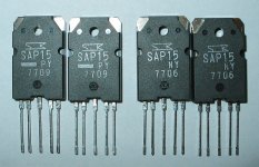
Another thing is output devices are Sanken SAP15N and SAP15P. With all these fakes around, not sure, I can find two original pairs... Or are there any drop in replacements?
I really wish I could help him with this...
He has sent to repair to someone and in the process that guy has blown the only remaining working pair also...
Another thing is output devices are Sanken SAP15N and SAP15P. With all these fakes around, not sure, I can find two original pairs... Or are there any drop in replacements?
I really wish I could help him with this...
Guess without the circuit and legit source of SAP15, the amp is doomed... Unless butchered to use a different power stage 🙁
Sanken SAP16N/P and similar family parts such as SAP15N/P were darlington pair complements with internal diodes for thermal compensation. Standard darlingtons won't have this feature. They also had internal emitter resistors which led to problems so the emitter resistors were deleted in current Sanken replacements, STD03N/P Note - these are NOT direct replacements for that reason:
http://datasheet.octopart.com/STD03P-Sanken-datasheet-15668856.pdf
HTTP 301 This page has been moved
Because emitter resistors are still required, they must now be fitted externally. See datasheets for original SAP16 types and compare for suitable resistor values.
http://datasheet.octopart.com/STD03P-Sanken-datasheet-15668856.pdf
HTTP 301 This page has been moved
Because emitter resistors are still required, they must now be fitted externally. See datasheets for original SAP16 types and compare for suitable resistor values.
Last edited:
Sanken SAP16N/P and similar family parts such as SAP15N/P were darlington pair complements with internal diodes for thermal compensation. Standard darlingtons won't have this feature. They also had internal emitter resistors which led to problems so the emitter resistors were deleted in current Sanken replacements, STD03N/P Note - these are NOT direct replacements for that reason:
http://datasheet.octopart.com/STD03P-Sanken-datasheet-15668856.pdf
HTTP 301 This page has been moved
Because emitter resistors are still required, they must now be fitted externally. See datasheets for original SAP16 types and compare for suitable resistor values.
You came for my rescue, yet again! Thanks Ian...
By the way so lifting up the Emitter Pin and soldering a 0.22Ohm 4W resistor in series to the previous emitter pad on PCB will be enough to do this "replacement"?
Hope the bias adjustment process would remain the same? So would be the bias values?
I can't guarantee that you will be able to do a simple conversion as I haven't done it myself and don't know the MF A3.2 layout. Otherwise, that is what I understand from posts here, is an acceptable procedure when the original parts are unobtanium. The bias settings should be the same but I expect some adventurous repairers will have found these can be tweaked since the resistors are no longer heated by the chip.
If this is too difficult, you may still be able buy the obsolete SAP16N/P as direct replacement parts from reliable suppliers like Profusion (UK and Europe)
http://www.profusionplc.com/pro/gex/manuftable? See and carefully read the relevant datasheets on their site. Note the pin sequence is mirrored between N to P types for all types and there is a missing pin on the STD series. Always search component details thoroughly as close to original as possible to avoid mistakes and check the advice you receive.
I can't guarantee that you will be able to do a simple conversion as I haven't done it myself and don't know the MF A3.2 layout. Otherwise, that is what I understand from posts here, is an acceptable procedure when the original parts are unobtanium. The bias settings should be the same but I expect some adventurous repairers will have found these can be tweaked since the resistors are no longer heated by the chip.
If this is too difficult, you may still be able buy the obsolete SAP16N/P as direct replacement parts from reliable suppliers like Profusion (UK and Europe)
http://www.profusionplc.com/pro/gex/manuftable? See and carefully read the relevant datasheets on their site. Note the pin sequence is mirrored between N to P types for all types and there is a missing pin on the STD series. Always search component details thoroughly as close to original as possible to avoid mistakes and check the advice you receive.
STD03N and STD03P are available locally from Digi-key. My original part is SAP15NY and SAP15PY. I saw they match the spec with STD03NY and STD03PY sans the emitter resistor. 0.22Ohm is the internal resistor on SAP15NY and SAP15PY. So I guess I should be safe in that.
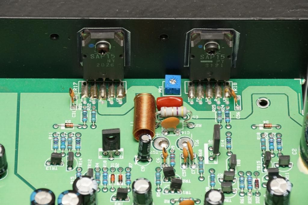
Here is the picture of burnt and ok channel(which was taken before he sent the amp to a "repair guy" for "repair", which came back dead on both channels.

You can see the burnt resistors and other stuff also on this pic. Even the 4.7Ohm Zobel resistor and it's series capacitor seem to be burnt? I will recheck them again, may be oscillations caused the transistors to die again, after the "repair guy" replaced them.
The "repair guy" all that has been changed by the guy who changed the transistors first time around. But my friend, bought those replacement transistors on ebay, so I also doubt their authenticity. Even that could be a contributing factor why the transistors died again. Also I have to check the trimmer pot, even an open trimmer pot also would kill it, wouldn't it?
Anyway right now the amp can power up on one channel. I first tried with series buld tester.. After removing fuses to blown channel. Later I powered full power also. but I was told that the stable channel also doesn't work. I am yet to test with a speaker though.
Here is the picture of the stable channel before they "repair guy" changed the original transistor. My friend bought this amp used on flea bay and shipped from US. And I can see from the picture that even the stable channel transistors, someone had replaced , even before the recent replacement by the "repair guy"
And by the way is there any way at all to get a Service Manual or schematics for amplifiers such as Musical Fidelity? Or do they solely make users to bring back the amp to their dealers or service center? Which in my case is not feasible or practical.
I did get another source for SAP15 though. But rather very expensive at $22+shipping for a piece. Really I am tempted to do STD03(The name sounds so wrong!) with an addon 0.22 emitter resistor. I really would(and all willing to) pay a pretty penny, if I could find a schematic anywhere.
http://www.bdent.com/catalogsearch/r...q=Sanken+SAP15
http://www.bdent.com/catalogsearch/r...q=Sanken+SAP15
Last edited:
I should have some original Sanken SAP15P and SAP15N in my parts box. Will look for them and let you know.
I should have some original Sanken SAP15P and SAP15N in my parts box. Will look for them and let you know.
That will be awsome! Thanks a lot. Really appreciate it, I will await your message and then we will take it up from there..
If R27, 127, C18 or C118 had burnt , serious oscillation would certainly have occurred but this won't suddenly happen unless the operating conditions changed radically. Those Zobel network parts shown don't actually look heat damaged to me.
You may have realised that there aren't really any service manuals on the net for MF products. There are several "temporarily unavailable file" messages but in effect, the answer is no. The only free information is in the form of hand drawn circuits for older popular models, posted across the web and occasionally here by other frustrated DIYs. Google is your friend if searching.
For buying parts I would still use Profusion. The SAP16 are uprated SAP15 but will replace them and cost only 3.33 GBP in small qty.
If R27, 127, C18 or C118 had burnt , serious oscillation would certainly have occurred but this won't suddenly happen unless the operating conditions changed radically. Those Zobel network parts shown don't actually look heat damaged to me.
You may have realised that there aren't really any service manuals on the net for MF products. There are several "temporarily unavailable file" messages but in effect, the answer is no. The only free information is in the form of hand drawn circuits for older popular models, posted across the web and occasionally here by other frustrated DIYs. Google is your friend if searching.
For buying parts I would still use Profusion. The SAP16 are uprated SAP15 but will replace them and cost only 3.33 GBP in small qty.
So the SAP16 can be directly substituted in place of SAP15?
STD03 is locally available here in Singapore from Digi-Key, coupled with the hearsay about it's superior reliability over SAP devices are the alluring factors. 🙂
Nah, I never expected to get the schematics FOC, but I am appalled by the fact that, there are no paid options as well... So once MF stops supporting the product, there is no-way it can be repaired?
Even those small and cheap players like Tangent make their schematics and Service manuals available... Emailing MF is useless I presume?
I know how you feel. I have an A5 system that now needs service but the quotes are high even to inspect and transport costs are also expensive. All that MF earns with their total non-disclosure policy is a "never again" vote from me.... So once MF stops supporting the product, there is no-way it can be repaired?....
I think your dealer is Audio Note in Singapore but as you didn't buy the product new, you won't get much sympathy but they should supply the service manager's details and workplace. If there is no service agent in your region, you might have a case for asking but I think that unless you are bound by a formal business agreement like service agents, MF won't discuss it and just refer you to someone else who is. 'Problem is, customers don't want to pay today's labour rates and like to think they can do it themselves which requires a lot more study and effort than a couple of hours on the bench, repacking and filling out a work sheet.
Service agents don't routinely destroy old model details, so repairing legacy products should be possible with any agency still holding the relevant manuals and with access to parts. Ask them directly as MF probably don't know who holds what documents after so many years. I don't know where you stand with newer agencies, though.
Ronj, I still have 4 of them: 2 x SAP15N and 2 x SAP15P
PM sent 🙂
I know how you feel. I have an A5 system that now needs service but the quotes are high even to inspect and transport costs are also expensive. All that MF earns with their total non-disclosure policy is a "never again" vote from me.
I think your dealer is Audio Note in Singapore but as you didn't buy the product new, you won't get much sympathy but they should supply the service manager's details and workplace. If there is no service agent in your region, you might have a case for asking but I think that unless you are bound by a formal business agreement like service agents, MF won't discuss it and just refer you to someone else who is. 'Problem is, customers don't want to pay today's labour rates and like to think they can do it themselves which requires a lot more study and effort than a couple of hours on the bench, repacking and filling out a work sheet.
Service agents don't routinely destroy old model details, so repairing legacy products should be possible with any agency still holding the relevant manuals and with access to parts. Ask them directly as MF probably don't know who holds what documents after so many years. I don't know where you stand with newer agencies, though.
Alpha Audio is the dealer in Singapore. And this is what MF website says
"If your unit is older and your dealer is unable to help you can contact our service department on +44 (0)20 8900 2866, Mon-Fri, 9-5pm GMT. We will arrange a time for you to deliver the item to us including a completed returns form. Our address for delivery and collection of your unit can be found on our contact page. Once the work has been carried out, we will contact you and arrange an appointment for you to collect your unit."
It makes no economical sense whatsoever to ship back and forth to UK. And my friend would never want to do it. We would rather butcher it and add a power stage of our own, if nothing works. For now, I will start replacing the transistors and see how it goes 🙂
I am sure it's fixable. The circuit does not look all that complex.
Why don't you have a go at drawing the circuit up.
That way we can help you and you can do hundreds (thousands?) of frustrated MFA owners and repairman.
Why don't you have a go at drawing the circuit up.
That way we can help you and you can do hundreds (thousands?) of frustrated MFA owners and repairman.
I successfully changed the blown SAP devices with a STD03 device and used a 0.22Ohm external resistor. Tried first one one channel. And it's working.
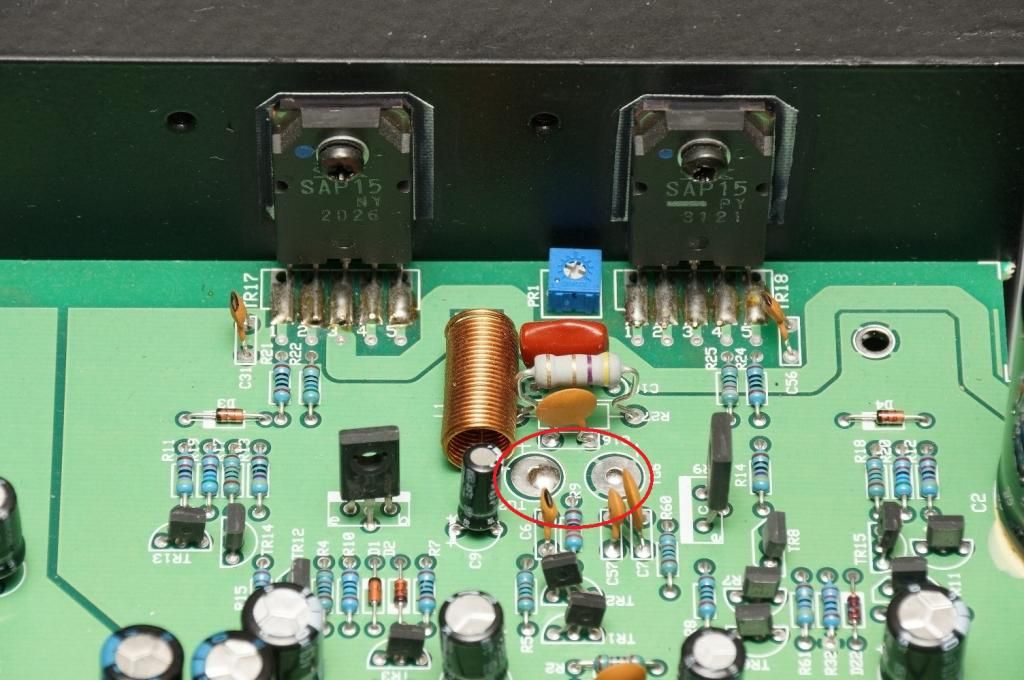
The failure cause probably for that channel was an open PR101(as seen in the pic) trim pot. I used a new 100Ohm same brand/value (Bourn's 3362P-1-101LF) trimmer and the channel seem to be working. Now the difficult part how to adjust the idling current?
On the MF 3.2 board there are two test points as shown in the below picture circled in red. But I do not know, what reading I should expect. Anyone has a clue?
On SAP15 Datasheet it is stated
1. Recommended Operating Conditions
➀Add a variable resistor (VR) between diode terminals to adjust the idling current. The
resistor having 0 to 200Ω is to be used.
➁Adjust the forward current flowing over the diodes at 2.5mA.
➂Adjust the idling current at 40mA with the external variable resistor.
But again I do not know how to adjust for this 40mA or 2.5mA.
Last edited:
You fitted 0.22 ohm emitter resistors and these are in series with the output stage from + to - rails, right? So measure the voltage across those resistors (I assume you fitted at least 3W rated ones). I'd measure across both resistors in series for 0.44 ohms and calculate the current by ohms law with a little more accuracy. Transposing, you need to measure 17-18 mV across the total 0.44 ohms or about 9mV across a single resistor, for 40 mA bias. Of course this is only for one channel, so it has to be repeated.
Because you could not gain access to the resistor, The SAP15 pairs had to be set up in the way specified but this is not a SAP15 pair, is it? You now have the external resistor available for measurement and bias setting at all times. Begin with the resistance set for least bias current to avoid thermal runaway. This 40mA figure has no refererence to MF specifications which could be quite different - ask around if you can.
Because you could not gain access to the resistor, The SAP15 pairs had to be set up in the way specified but this is not a SAP15 pair, is it? You now have the external resistor available for measurement and bias setting at all times. Begin with the resistance set for least bias current to avoid thermal runaway. This 40mA figure has no refererence to MF specifications which could be quite different - ask around if you can.
Last edited:
- Status
- Not open for further replies.
- Home
- Amplifiers
- Solid State
- Helping a Friend:- Musical Fidelity A3.2 Integrated Dual Mono Schematics and SAP15