Dear Friends,
After a few projects, mostly amplifiers, I decided to try to build an integrated AMP/streamer/DAC, in one case. The amp is an LM3886 kit, with the power supply section on board and the streamer/dac is a Raspberry Pie with Dac hat on top.
I am using Toroidal 18-0-18/60VA and the supply for the raspberry is a meanWell 5V/3A SMPS.
The switch is a Classic 230V Antivandal Switch with an integrated led, supplied by 230AC.
Before putting everything into the case, I´ve tried to connect everything, and it worked like it should. When trying, I had the Transformer and the smps each connected separately to the mains.
Yesterday, I was trying to put everything into the case But once I´ve finished everything and turned it on, The smps started, but the amp section just did not start. I wasn´t sure what was going on, so I measured everything, and it seems, one of the secondaries is faulty, giving around 2volts.
I would like to ask if I connected it wrong. I´ve put together a simple schematics, how I connected it. Basicaly my idea was to connect the smps and the transformer "in parallel", with the switch switching only Live wire. The led goes to both Live and neutral.
Schematic_K Amp DAC_2021-02-27_09-25-13.pdf - Google Drive
usp=sharing
Thank you very much for your advice.
Adam
After a few projects, mostly amplifiers, I decided to try to build an integrated AMP/streamer/DAC, in one case. The amp is an LM3886 kit, with the power supply section on board and the streamer/dac is a Raspberry Pie with Dac hat on top.
I am using Toroidal 18-0-18/60VA and the supply for the raspberry is a meanWell 5V/3A SMPS.
The switch is a Classic 230V Antivandal Switch with an integrated led, supplied by 230AC.
Before putting everything into the case, I´ve tried to connect everything, and it worked like it should. When trying, I had the Transformer and the smps each connected separately to the mains.
Yesterday, I was trying to put everything into the case But once I´ve finished everything and turned it on, The smps started, but the amp section just did not start. I wasn´t sure what was going on, so I measured everything, and it seems, one of the secondaries is faulty, giving around 2volts.
I would like to ask if I connected it wrong. I´ve put together a simple schematics, how I connected it. Basicaly my idea was to connect the smps and the transformer "in parallel", with the switch switching only Live wire. The led goes to both Live and neutral.
Schematic_K Amp DAC_2021-02-27_09-25-13.pdf - Google Drive
usp=sharing
An externally hosted image should be here but it was not working when we last tested it.
Thank you very much for your advice.
Adam
Hi Adam
First try to but step by step your "modules" in the case and try which measure faulty.
missing on your schematic is the rectifier after the transformer !!! and you have to connect the 0V after your transformer to the main earth (chassis) properly. after the rectifier you need some electrolytic caps for each rail. e.g. 6800µF/35V.
Your LM3886 kit is stereo and i guess you are a bit under powered. from a 18-0-18VAC trani you will get about 25VDC idle voltage on each rail after rectifier. you use a 60VA transformer and so you get 30VA for each channel. that is on the minimum side to play music. if you want to go louder and especially if you have 4R speakers you need a much bigger transformer.
regards
chris
ps
2nd link is not working
Hi Chris,
Thank you very much for your reply.
I tried to keep the schematic as simple as possible. The Amp module has it´s own "supply" section, with proper rectifier and Caps. The 0V after transformer is not connected to the Earth, but I had no issues with that(could this be a problem?). The Amp, before including the dac was playing without any issues. The Chassis, and the SMPS are both connected to Earth.
As I mentioned, I had the amp with the transformer connected before, and the loudness wasn´t an issue. Could this fry the transformer?
My question basically is, how to implement the Streamer/DAC properly. That means the connection between mains, transformer, smps and switch.
Is it ok to connect both smps(Streamer/DAC) and transformer(AMP Section) in parallel, and if so, is any other connection, than that on the picture needed?
Both attachments are the same pictures btw.
Thank you very much,
Adam
Hi
Generally its not a problem to switch on 2 x SMPS or 2x transformer or mix this supply. you wrote
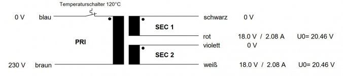
so I measured everything, and it seems, one of the secondaries is faulty, giving around 2volts. a 60VA 18-0-18VAC transformer have a current capability of max 1,66A.so 30VA for each channel .... with a dynamic reserve of 33% means you get about 20VA for each channel for your output power. this means that you do not get more then 1Ampere for your amps. not all transformer have a primary fuse..if you pushed the amps on the limit of the current of the transformer then its possible that your NTC primary "fuse" get broken. see picture
Generally its not a problem to switch on 2 x SMPS or 2x transformer or mix this supply. you wrote
so I measured everything, and it seems, one of the secondaries is faulty, giving around 2volts. a 60VA 18-0-18VAC transformer have a current capability of max 1,66A.so 30VA for each channel .... with a dynamic reserve of 33% means you get about 20VA for each channel for your output power. this means that you do not get more then 1Ampere for your amps. not all transformer have a primary fuse..if you pushed the amps on the limit of the current of the transformer then its possible that your NTC primary "fuse" get broken. see picture
Attachments
Last edited:
Hello Chris,
So I dissassembled everything, measured the transformer, and actually found out, that I had a bad contact due to the enamel coating of the winding. It´s a basic mistake I suppose, but at least I am happy I managed to find out the cause of the problem and I do not have to buy a new Transformer. Everything is working now, and it´s finished.
Anyway, thank you very much for your help, appreciate it a lot.
Regards,
Adam