I have a yamaha C1 power board. The 100V section keeps blowing a 1k resistor. I have new tip40 power transistors and diodes and caps are new.
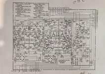
Here is the schematic. Far left section, resistor marked R2012 and R2011.
I don’t have an Oscope! Can anyone explain this part of the board? TR 2003 & TR 2004 have been replaced also. Thx Guys
Here is the schematic. Far left section, resistor marked R2012 and R2011.
I don’t have an Oscope! Can anyone explain this part of the board? TR 2003 & TR 2004 have been replaced also. Thx Guys
Attachments
Last edited:
You have replaced =TR2003&TR2004 ---were they faulty ?
If not and the replacements are testing okay and both 1K resistors are still blowing and the two diodes you say you have changed relating to the feeds for those resistors are testing okay and the right way round and both 39K resistors are near the right value in the same circuit then the high current logically should come via the diode feeds not via the 39K resistors.
What current is flowing at the diodes output sufficient enough to blow the resistors ?
High current must have two electrical points to cause current flow in and out , so if the diodes are okay then that leaves the flow via the small value capacitors ,which would be unlikely but possible .
Check for a short circuit round those components.
Thanks!
It is hard to test the power (where it flows etc) as the board runs off of a huge muti-phase transformer and I have no power supply. So unless I can get to the point where nothing burns or over heats I can’t test it in circuit, plugged back in. The TR 2002 transistor was burned out from overheating. The other side, the TR 2003 was ok.
I tested the diodes (while attached to the board) so I will replace them all as well as the caps. I replaced the 39k resistors as a preventative measure but they measured within spec when pulled. Thanks for your observations! If you would like to see the actual board I can post a close-up view of it. Noel