Looking to buy an r-core transformer but am a bit confused by the four wires which are below;
0 - Black
115V - Green
230V - Red
Green/Yellow - Scn
I am 99% sure that it should be wired to a 230V IEC connector (in the UK) as configuration below;
Red - Live
Black - Neutral
Green/Yellow - Earth (soldered to the chassis next to the earth wire from the IEC connector).
If I am wrong, can anyone correct me please.
Thanks
That is correct. You can put a double pole switch in series for isolation if you desire.
There will no doubt be loads of comments regarding earth bonding. A mechanically sound joint, before it is either soldered or crimped, is fine.
There will no doubt be loads of comments regarding earth bonding. A mechanically sound joint, before it is either soldered or crimped, is fine.
a joint that holds together without any solder/glue. A bolt/screw through a wire loop complies.
It is very unusual to have a centre tapped primary.
Are you sure your primary is Blk, Grn, Red?
Two wires is common for a 230Vac primary
and 4 wires is common for a "universal" 115/230Vac primary.
Is your IEC socket fused and/or switched?
If it is neither, then IEC Live goes to Fuse. The fuse and neutral then feeds into a 2pole mains switch.
The switched Live and Neutral then feeds the transformer and other auxiliaries.
I often build without a switch. I just omit the switch. It saves running Mains voltage wires around inside the equipment.
I just pull out the IEC plug, or switch off at the wall socket outlet.
Last edited:
Cheers Andrew
Enclosed is a picture of the transformer showing the wires I'm not sure what a centre tapped primary is.
I live in Scotland, I'm certain that the IEC socket is not fused or switched, the IEC Live always goes to fuse.
I'm sure that the configuration above is correct, I just wanted to be certain.
I will be using an on/off switch which is already built into the enclosure and will be be using the Live connection to facilitate this.
Attachments
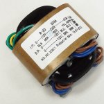
That label does look like it shows a tapped primary.
A bit unusual.
Insulate the 115Vac tapping, so that it can never short to anything.
Use the Blk & Red as your 240Vac primary connections.
I hope it is designed to be suitable for our 253Vac maximum !
The maximum continuous AC current from each secondary is 1.25Aac.
After rectifying and passing through a capacitor input filter the maximum continuous DC current is ~625mAdc
If you load is constant then you should design for using approximately 50% of that maxmum rating to keep the transformer fairly cool.
i.e. aim for a continuous duty of <320mAdc.
Low duty cycle can be much higher transient current.
The (two Live) wires going to the fuse must be a twisted pair.
The wires (L+N) going to the switch must be a twisted pair.
The wires (L+N) going to the transformer must be a twisted pair.
Do you see the message?
Last edited:
I hope it is designed to be suitable for our 253Vac maximum !
Good point, are EI transformers suitable for the max of 253Vac?
All mains powered electrical equipment sold/manufactured in the EU must comply with the requirements for safety with our harmonised voltage.
Importers of foreign manufactured goods must be responsible for the safety of their imported goods.
We hear regularly of importers having illegal goods getting seized because of ignorance or disregard of safety rules.
If you become the importer, then you are responsible for your safety. Did you ask?
No, and taking this into consideration, I think I will probably just go for an EI transformer from a reputable UK company.
Cheers
Cheers
After rectifying and passing through a capacitor input filter the maximum continuous DC current is ~625mAdc
If you load is constant then you should design for using approximately 50% of that maxmum rating to keep the transformer fairly cool.
i.e. aim for a continuous duty of <320mAdc.
Low duty cycle can be much higher transient current.
I have no real idea what this means and would it only apply to an R-core transformer?
The (two Live) wires going to the fuse must be a twisted pair.
The wires (L+N) going to the switch must be a twisted pair.
The wires (L+N) going to the transformer must be a twisted pair.
Do you see the message?
Is the above to cancel out EMI or has it a lot to do with designing with an r-core transformer?
Quote:
Originally Posted by AndrewT View Post
After rectifying and passing through a capacitor input filter the maximum continuous DC current is ~625mAdc
If you load is constant then you should design for using approximately 50% of that maxmum rating to keep the transformer fairly cool.
i.e. aim for a continuous duty of <320mAdc.
Low duty cycle can be much higher transient current.
There is a limit to the current you can draw from any transformer.I have no real idea what this means and would it only apply to an R-core transformer?
Quote:
Originally Posted by AndrewT View Post
The (two Live) wires going to the fuse must be a twisted pair.
The wires (L+N) going to the switch must be a twisted pair.
The wires (L+N) going to the transformer must be a twisted pair.
Do you see the message?
Any and every wire passing a varying current emits emi.Is the above to cancel out EMI or has it a lot to do with designing with an r-core transformer?
Ok, thanks for all the help, I really do appreciate it.
I have bought a 36VA transformer which will be more efficient than a 30VA and plan to put aluminium heatsink around it to prevent it emitting RFI/EMI.
Also I will be twisting both wires to the fuse, switch and transformer as well as the secondary windings.
Again, thanks for your help.
I have bought a 36VA transformer which will be more efficient than a 30VA and plan to put aluminium heatsink around it to prevent it emitting RFI/EMI.
Also I will be twisting both wires to the fuse, switch and transformer as well as the secondary windings.
Again, thanks for your help.
(I learned this way:
ElectroMagnetic...
Emittion
Immunity
Compatibility
If Immunity is higher than Emittion (at every frequency), than you get Compatibility, otherwise
Radio Frequency Interference.)
A mains transformer generally have 10 to 1000 times higher flux emittion than a pair of wire carriyng differential current of primary.
Last edited:
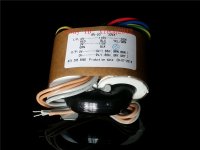
How to wire the primaries of this guy for 230V?
I could not find any info on net.
Andrew, please...
Tie green to blue and insulate well. Red and black become the inputs.
- Status
- Not open for further replies.
- Home
- Amplifiers
- Power Supplies
- Help with wiring r-core transformer