Help with VU meter amplification made of an Ampere Meter:
Hello!
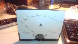
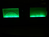
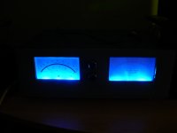
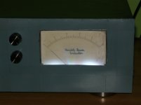
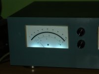
I have got hold of 3 measuring instrument displays 10 x 8cm big!
1st had the torsion wire broken
2nd works fine with a 200k pot and a diode
3rd one is an ampere meter display but the signal is too low all the time. On the speaker line it work well. 100k pot, diode in the contraption.
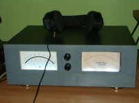
I will post some pics later.I intend to use them both with pots on the rec out line of the amplifier so that they can be a friend talk subject every time they visit.
I am adjusting them from the pots based on Peak Search CD on the highest signal recorded of the Cd that I have in the house with a quarter of its range left out of the beat of it so that it has a safety margin for every time I play back sound with them being in the scene.
Hello!
I have got hold of 3 measuring instrument displays 10 x 8cm big!
1st had the torsion wire broken
2nd works fine with a 200k pot and a diode
3rd one is an ampere meter display but the signal is too low all the time. On the speaker line it work well. 100k pot, diode in the contraption.
I will post some pics later.I intend to use them both with pots on the rec out line of the amplifier so that they can be a friend talk subject every time they visit.
I am adjusting them from the pots based on Peak Search CD on the highest signal recorded of the Cd that I have in the house with a quarter of its range left out of the beat of it so that it has a safety margin for every time I play back sound with them being in the scene.


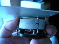
If you decrease the resistor this make the Ammeter suitable for bigger currents.Will try! Dough can't i decrease the value of the resistor with another resistor or cancel it out?
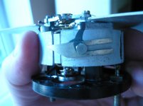
You must remove this,then the Ameter is probably suitable for 1mA OR 10mA or so...
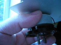
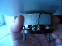
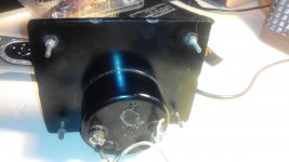
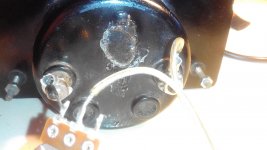
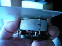
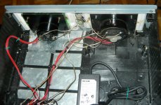
In the first picture I can see the top and bottom of the moving coil. One wire goes from the top of it to an input terminal. There also is a wire from the bottom of the coil to the other terminal. Nothing else should be connected. I see what looks like a small coil that may be in the circuit and what may be a terminal board that ties the coil in. But not quite enough views to be sure of the wiring. So removing one wire from the terminal board connecting to the small coil should do it.
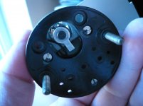
It looks like you'll have to remove all of the resistors from the thing. It will most likely be either a 200uA or 500uA coil with roughly 1k of series resistance.
I'd recommend building a proper driver circuit once you isolate the coil. I wrote a piece a while back that detailed a very sensitive, simple and effective circuit using readily available circuits (and no germanium diodes which are a complete pain to source and construct with).
Driving VU and other AC Meters - Simple High Performance Circuits
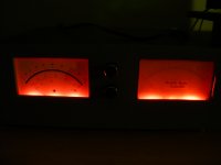
Well came to the folowing conclusion, I am leaving one to beat together with the amplifier the ampere meter that being and the other one on the left channel of the amplifier rec out for the tape. In this case I will have a signal power indicator for the one with increased sensitivity and the other one will beat on the power that will go increasing or decreasing on the amp according to the desired listening level, this time again on the left channel of the amplifier too. They don't mach visualy but so, separately they do a great job and conquer the day when it comes to them functioning in the both of worlds! Thanks you!
Attachments
- Status
- This old topic is closed. If you want to reopen this topic, contact a moderator using the "Report Post" button.
- Home
- Source & Line
- Analog Line Level
- Help with VU meter amplification made of an Ampere Meter