I built a prototype cabinet for PA use. First time doing a ported design.
2x12 Faital 12PR300 woofers, 2.5 way.
3.0 ft^3 box is tuned to 70Hz.
2 vents, each 1.5" x 10"
Planning to cross to subs at 80-100Hz.
Low woofer LP at 300Hz, mid-woofer plays up to 1" horn @ 1.3kHz.
Damping mat/ 1" foam on the inside walls.
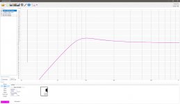
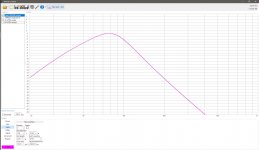
I designed this cabinet using using WinISD. The SPL response shows a moderate hump centered at 100Hz before the roll-off. I was going to EQ this flat and adjust the roll-off to keep the excursion under control at high power.
Problem is, the actual bass response is way off from the sim. There is no hump at 100Hz, but instead a shallow roll-off starting somewhat too early. I'm concerned that I won't get enough SPL out of this before the woofers tear themselves apart, since I cut it close already with the box tuning to push the port resonances past the crossover. In the sim I had to cut the knee to make a nice crossover slope, in real life it looks like I'll need a boost.
The impedance peaks match fairly well between simulation and reality - the lower one is off by a few Hz but the peaks are the same height, and the belly shows a Fb of 70 in both cases.
I have 1" foam on the inside walls, but it's well away from the vents, and no volume filling.
Can anyone offer some insight into what's happening here? I've gone over my set-up like a dozen times (meaning - I haven't accidentally put a HP filter on the woofers)
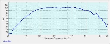
These measurements were made outdoors away from any reflective surfaces. The ground plane plot was taken at 10 feet. The woofer and port near field plots are not normalized, they are both taken at a few inches away (at a lower drive level)
Thanks!
2x12 Faital 12PR300 woofers, 2.5 way.
3.0 ft^3 box is tuned to 70Hz.
2 vents, each 1.5" x 10"
Planning to cross to subs at 80-100Hz.
Low woofer LP at 300Hz, mid-woofer plays up to 1" horn @ 1.3kHz.
Damping mat/ 1" foam on the inside walls.
I designed this cabinet using using WinISD. The SPL response shows a moderate hump centered at 100Hz before the roll-off. I was going to EQ this flat and adjust the roll-off to keep the excursion under control at high power.
Problem is, the actual bass response is way off from the sim. There is no hump at 100Hz, but instead a shallow roll-off starting somewhat too early. I'm concerned that I won't get enough SPL out of this before the woofers tear themselves apart, since I cut it close already with the box tuning to push the port resonances past the crossover. In the sim I had to cut the knee to make a nice crossover slope, in real life it looks like I'll need a boost.
The impedance peaks match fairly well between simulation and reality - the lower one is off by a few Hz but the peaks are the same height, and the belly shows a Fb of 70 in both cases.
I have 1" foam on the inside walls, but it's well away from the vents, and no volume filling.
Can anyone offer some insight into what's happening here? I've gone over my set-up like a dozen times (meaning - I haven't accidentally put a HP filter on the woofers)
These measurements were made outdoors away from any reflective surfaces. The ground plane plot was taken at 10 feet. The woofer and port near field plots are not normalized, they are both taken at a few inches away (at a lower drive level)
Thanks!
Attachments
Did you lay the speaker down on the side while measuring it? If you didn't (measuring it standing up), the upper driver does not have the same air coupling as the lower one on a ground plane measurement.
How did you simulate the 2,5 way in winisd? I didn't know it can simulate it since you can only apply the filter for all drivers at the same time.
How did you simulate the 2,5 way in winisd? I didn't know it can simulate it since you can only apply the filter for all drivers at the same time.
WinISD doesn't take account of bafflestep, so the loss of half-space loading as frequency decreases from the mids on down will give something like what you've measured ie perceived loss of bass relative to the model.
1.5"x10" vents? Is that 2x 1.5" tubes 10" long? That tuning seems wrong for 70hz in 3cubes? Or a rectangular vent 1.5x10 inches in area?
Last time I built a mid/top box, it was about 2 cuft and 60hz tuning. Ports were about 70mm dia and barely 20mm long.
I think you've probably tuned your box very low if those ports are 1.5" round and 10" long tubes and that's why theres no punch and a slow rolloff. You've basically made a sealed box tuning wise.
A quick check shows yu'd basically need to cut 2x3" ports only as thick as the wood itself to get around 70hz in 3 cuft.
Last edited:
>>A quick check shows yu'd basically need to cut 2x3" ports only as thick as the wood itself to get around 70hz in 3 cuft
Ports are 1.5" x 10" rectangular, and very short. Large area to get the air velocity low at peak SPL.
Box is indeed tuned to 70Hz per impedance plot.
>>Did you lay the speaker down on the side while measuring it? If you didn't (measuring it standing up), the upper driver does not have the same air coupling as the lower one on a ground plane measurement.
>>How did you simulate the 2,5 way in winisd? I didn't know it can simulate it since you can only apply the filter for all drivers at the same time.
I'm going to try measuring again with the cabinet on it's side. I didn't think baffle step would make a difference at these frequencies.
Also I made the measurements with both woofers playing full range, which is what I assumed WinISD is doing. Tilted the cabinet to be on-axis at mic position.
Last edited:
and a question about WinISD:
does it simulate the response in free-space?
No, it uses half space.
Also I made the measurements with both woofers playing full range, which is what I assumed WinISD is doing.
It is.
Tilted the cabinet to be on-axis at mic position.
To do that is correct. Though, in the bass the phase error is that low, it would not make much difference. At 150Hz the wave length is 2,29m, an offset of 10cm would not be noticable in the plot, that's well within the measurement tolerance. At the low mids that starts to get important but above the bass it's better to measure free standing (and in most cases gated).
I would suggest you check your measurement chain. Make a loop back and measure (sweep) what the sound output and mic back in got as response. After that check your mic compensation file. Both can have a huge impact on the result as many sound cards got a high pass on the output and mics got their biggest non-linear range at the lower and upper end.
Edit: Did you break in your drivers? Did you measure the TSP? I mean, the simulation can only be correct if the parameters are the same or at least close to the actual driver.
Last edited:
After more testing, I am of the opinion that the difference in my sim vs. measured FR is due to baffle step along with various added-up cabinet losses (I also didn't adjust Q factors in WinISD)
I am going to EQ to target crossover response and try to get an idea of excursion with the paper-triangle-taped-to-the-cone-meter to see where the limits are.
Thanks for the responses.
I am going to EQ to target crossover response and try to get an idea of excursion with the paper-triangle-taped-to-the-cone-meter to see where the limits are.
Thanks for the responses.
One last thing to consider is that WinISD (and others) simulate for pistonic cone motion at all frequencies.
As you move up in frequency, that assumption fails.
Chris
As you move up in frequency, that assumption fails.
Chris
One last thing to consider is that WinISD (and others) simulate for pistonic cone motion at all frequencies.
As you move up in frequency, that assumption fails.
Yes, that's correct. The higher the frequency, the more the response diverts from that. Most drivers got an increase of level at the upper bass or in the mid, not all though.
After more testing, I am of the opinion that the difference in my sim vs. measured FR is due to baffle step along with various added-up cabinet losses (I also didn't adjust Q factors in WinISD)
You have to add the actual serial resistance of the contact resistances, even if you go active it's going to be ~0,5 Ohm. For passive the serial resistance of the coil(s) has to be added too to get a reasonably fitting simulation. That, ofcourse increases the Qt, changes the needed enclosure size (it get's bigger, on high Qts drivers sometimes vastly) and changes the tuning.
I am going to EQ to target crossover response and try to get an idea of excursion with the paper-triangle-taped-to-the-cone-meter to see where the limits are.
Like chris661 already wrote, WinISD can do that calculation better. Additionally, if you leave out the low cut below the tuning frequency, the excursion will be a lot higher and the driver will distort much earlier.
Yesterday I did more testing.
I placed the mic at 4m and made a groundplane measurement at 120db.
This should be a 1 meter SPL of 126dB, correct? (+12dB for the quadrupling of distance, -6dB for the ground plane) I don't think my mic works well at over 120db.
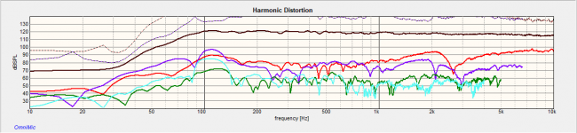
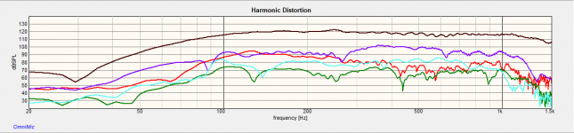
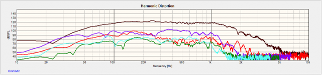
The first plot shows an earlier full range measurement at 1m (HP filter on the woofers was not refined)
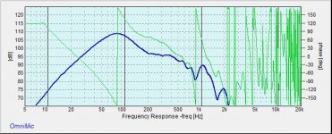
Second plot shows woofers only at 4m, fairly precise LR24@100hz, with an added lowcut filter at 40hz.
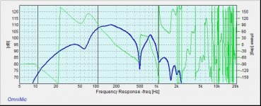
Third plot shows response at 4m with no lowcut.
Third harmonic in the lower mids, and second harmonic in the tweeter channel are concerning to me but I don't know what is par for the course at these levels.
So, what is considered acceptable distortion at this SPL?
What distortion level below the tuning frequency signals that xmax has been exceeded?
I placed the mic at 4m and made a groundplane measurement at 120db.
This should be a 1 meter SPL of 126dB, correct? (+12dB for the quadrupling of distance, -6dB for the ground plane) I don't think my mic works well at over 120db.
The first plot shows an earlier full range measurement at 1m (HP filter on the woofers was not refined)
Second plot shows woofers only at 4m, fairly precise LR24@100hz, with an added lowcut filter at 40hz.
Third plot shows response at 4m with no lowcut.
Third harmonic in the lower mids, and second harmonic in the tweeter channel are concerning to me but I don't know what is par for the course at these levels.
So, what is considered acceptable distortion at this SPL?
What distortion level below the tuning frequency signals that xmax has been exceeded?
Attachments
I placed the mic at 4m and made a groundplane measurement at 120db.
This should be a 1 meter SPL of 126dB, correct? (+12dB for the quadrupling of distance, -6dB for the ground plane)
Well, generally, yes. Generally? Yes, that neglects that in the nearfield the drop of level is just 3dB per doubled distance instead of 6dB in the far field. In the bass the nearfield is quite short so for most cases it can be ignored since most measurement signal chains aren't level calibrated anyway.
I don't think my mic works well at over 120db.
Well, many measurement mics don't even go up to 120dB. The Behringer ECM-8000 distorts at 118dB (rated I think at 123dB), the Superlux ECM-888 is rated 128dB (one of my mics, though I haven't verified it, very useful with a laptop because it doesn't need phantom power), the beyerdynamic MM1 also 128dB, the Earthworks Audio M23 specs state impressive 140dB, the Earthworks Audio M30 142dB and NTI Audio M2211 the top of this list with 144dB. The order is ascending level and price (30-1400 bucks).
I've mentioned the Superlux ECM-888 because most measurement microphones start to work at 12V, some even as low as 3V but many do not achieve all ratings until they reach ~40V. The Superlux does not have that problem because the electret mic is powered by a battery, so it does not need phantom power at all. Very useful if you are in the middle of the pampa and got no source for phantom power or the laptop/tablet provides way to low PP.
The first plot shows an earlier full range measurement at 1m (HP filter on the woofers was not refined)
Second plot shows woofers only at 4m, fairly precise LR24@100hz, with an added lowcut filter at 40hz.
Third plot shows response at 4m with no lowcut.
Third harmonic in the lower mids, and second harmonic in the tweeter channel are concerning to me but I don't know what is par for the course at these levels.
Well, 120dB is probably already too much spl for the mic, it's hard to say which is the source from your measurements. To find that out you could set a speaker to a certain level (below the distortion range) and then measure how the distortion increases. Since the power of the speaker stays the same, the difference in distortion to the signal will be from the microphone itself. That's not very precise but gives you a ballpark number.
So, what is considered acceptable distortion at this SPL?
Heh. That depends on how well the audience reacts to suffering. 😀 The acceptance usually rises a lot with drinks and pills though. 🙄
The acceptable distortion level depends on many parameters, one of the most important ones is the frequency. At 2-3kHz and 5+7k are the most sensitive ranges, a dip in response at a resonances there is often very much preferred instead of a maximum linear response, a hi-shelf of -3dB for the tweeter is often used at PAs used near the upper spl range to make the sound less aggressive/harsh.
What distortion level below the tuning frequency signals that xmax has been exceeded?
Below the tuning frequency the sub doesn't provide any substantial sound levle, so it does not matter there. But too much excursion affect the frequencies above that aswell, the coil is then out of the linear range for these frequencies too, after all. A lowcut at or shortly below the tuning frequency is a MUST! If you don't have it, expect to have ~10dB (or more) less undistorted spl. And, well, your speakers. Let's say they won't reach retirement age if you keep going anyway. 😉
- Status
- Not open for further replies.
- Home
- Live Sound
- PA Systems
- Help with vented PA speaker design/testing