I posted this on audiokarma too and they were very helpful.
Someone put it in the recycling bin and I would love to get it working.
I'm new to vintage audio, but I can solder, and I have a multi-meter. I've also watched some tube safety videos.
The only name on it is Itala-tone with no other markings anywhere on it. If anyone knows anything about it that would be awesome.
I haven't turned it on yet because it doesn't have a fuse holder. I ordered one and it should be here this week hopefully.
Since it doesn't indicate the correct fuse to use, what amp fuse should I put in?
Do I need to test or do anything with the tubes before turning it on?
I've read the capacitors should be replaced first, but is it safe to make sure it works first before I invest in new caps? None of them appear to be leaking or bulging. I will definitely replace them if it works.
I have a can of deoxit so I'll spray all the switches and pots.
I was also wondering what the threaded plug is above the 2 jacks. In the other picture you can see it is wired in.
Thanks!
Attachments

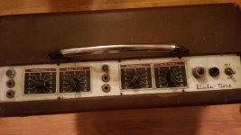
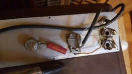
The plug above the jacks is a PL259 or miniature version, widely used in microphone back in the 60s.
Looks like Itala Tone? Nothing to report here.
If the caps are not short circuit, leave them alone and fire it up.
Looks like Itala Tone? Nothing to report here.
If the caps are not short circuit, leave them alone and fire it up.
You can modify your profile to include that information.
On the question of that amplifier, I would not recommend plugging it without a careful check out. Search for "dim bulb tester" and similar here and knock one together.
Better still would be a DC PSU or a variac to allow you reform electrolytics provided they are not too far gone.
Were it me I would check the transformers for shorts and replace all of the supply caps before ever plugging it in.
Updated my profile
Forgot to mention I did make a dim bulb tester yesterday. What watt bulb should I use?
New to all this so I'll have to read how to test the transformer.
Forgot to mention I did make a dim bulb tester yesterday. What watt bulb should I use?
New to all this so I'll have to read how to test the transformer.
jacks is a PL259 or miniature version, widely used in microphone back in the 60s.
It's not a PL259. It is a microphone jack. I believe that's what they were called. They are also found on old VTVM's (vacuum tube volt meter). It can be replaced with a standard 1/4 inch guitar jack.
What watt bulb should I use?
I would start with a 60 watt bulb. It MUST be a standard incandescent bulb. A CFL or LED bulb will not work here.
If it lights brightly, then dims down you can try a 100 watt bulb. If there is no dimming at all, and the bulb is at almost normal brightness you probably have a shorted capacitor.
Remove all tubes and try again. If the bulb is dim the transformer is likely OK. Add all tubes back EXCEPT the 5U4. The bulb should glow, then slowly dim as the tubes begin to glow. If adding the 5U4 causes a bright glow, it is bad, or one or more of the electrolytic capacitors is bad (likely).
Yeah looks like that's what the jack is called. Found some switchback adaptors that look like they would fit but I really don't need it, there are plenty of jacks. I was mostly just curious as to what it might be used for.
Thanks for the instructions 🙂
So if I get past the transformer test and put the tubes back in (no 5u4) and the bulb lights up, then would that indicate a bad tube or still maybe just a bad capacitor?
If I have a short, but the transformer seems to work ok, I think that would convince me to invest money into it and recap it.
Looks like I really don't have a choice anyway. I was reading in an antique radio forum about the tiny chief capacitors in my amp. This is what the guy said "I've never tested a Tiny Chief that wasn't leaky. I would recommend replacing them if you're planning on keeping the radio"
I'm still not sure what fuse I should use. I have some normal 2 amp fuses, will that be safe?
Agree^^^
That used to be the standard microphone connector.
It is the Switchcraft 2501. Actually 2501MP, MP for male and panel mount.
They are still available:
2501MP Switchcraft Inc. | Connectors, Interconnects | DigiKey
heck, I even have a bunch of them in stock.
That used to be the standard microphone connector.
It is the Switchcraft 2501. Actually 2501MP, MP for male and panel mount.
They are still available:
2501MP Switchcraft Inc. | Connectors, Interconnects | DigiKey
heck, I even have a bunch of them in stock.
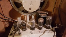
Fusing: find an amp with similar big-tubes. Two 6L6 and a 5U4 is a VERY common lineup. Fenders from 25W to 40W; also tons of PA amps. I'd guess for 120V power, 1 Amp should hold.
AGREE about starting it on a lamp-limiter. 60W to test for smoke, fire, explosion. I'd really expect the main filter cap to go phoooey and make a mess (when 5U4 is in).
Agree it is certainly worth restoring, even if it needs a lot of work.
AGREE about starting it on a lamp-limiter. 60W to test for smoke, fire, explosion. I'd really expect the main filter cap to go phoooey and make a mess (when 5U4 is in).
Agree it is certainly worth restoring, even if it needs a lot of work.
put the tubes back in (no 5u4) and the bulb lights up,
This should not happen since there is no high voltage present in the amp without the rectifier. This step only applies power to the heaters of the 4 remaining tubes, which should consume about 20 watts. Their resistance rises as they warm up, so the bulb should glow brightly, than slowly grew dimmer over a minute or two. It will never go completely dark, but should remain less than half brightness.
about the tiny chief capacitors in my amp. This is what the guy said "I've never tested a Tiny Chief that wasn't leaky. I would recommend replacing them if you're planning on keeping
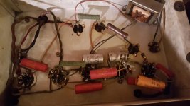
If I was rebuilding this with intend of keeping it, and maybe using it for a guitar amp, I would replace every capacitor in the thing, and measure every resistor, replacing any that are more than 20% off value. I can't find a readable date code on any part, but I'm guessing early 50's. Look for a 4 digit number on capacitors including the metal cans. The first two digits are the year that PART was made. Finding several parts with numbers within a year of each other will confirm the date that the parts were made. The actual amp can be the same year, or a year later than the highest numbered part.
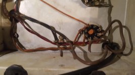
I can't tell from the picture if the speaker is PM (permanent magnet) or has a field coil. If there is no magnet on the speaker, it uses a field coil. There is a twisted pair of wires coming from the speaker that could be the coil winding. Measure this with an ohmmeter to see if their is continuity (50 to 1000 ohms is normal). If not the speaker will need replacement.
The red capacitor on the far left in the under chassis photo appears to be the "death cap." If it is connected from the power transformer primary (black wire) to chassis ground as it appears to be, REMOVE IT. If this capacitor fails it will connect the power line to the chassis, which is connected to the ground side of the input. If you plug a guitar into this, it could be connecting your guitar to the power lines! Replace the old power cord with a modern power cord (cut the socket end off an extra computer power cord) and connect its green (or green and yellow) wire to chassis ground.
I have an old Stromberg Carlson PA amp of about the same vintage, but more powerful. If the transformers are good, I plan to replace all the small parts (caps and resistors) and put a guitar jack in place of the microphone connector. I used the same amp for guitar duty when I was in high school, and I'm trying to recreate the same amp. Did it sound as good as I remember, or did I like it because it was LOUD!
Tried to find some part numbers, but without taking any off the only visible number is 4774-1 on the 25-25 capacitor.
Has Stackpole pots, but no numbers on those that I could see either.
Speaker has a magnet and I think the only wires coming out of it are the connections. Speaker is also connected to the back panel to just a 1/4 jack.
The left red capacitor is connected to the black wire from the transformer, and ground to the chassis. I will remove it, but do I need to replace it?
I played guitar for about 5 or 6 years but never really got any good at it despite lessons and much practice 🙁
I still have a couple guitars left so hopefully I can get this thing working. My wife thinks I'm just going to electrocute myself but the safety rules I've read so far are pretty straightforward.
I will remove it, but do I need to replace it?
No, you do not want a capacitor in that spot at all. Adding the three wire cord with it's green wire connected to the lug where the CHASSIS end of that cap was connected is the safest option, and the way all modern electronics with metal chassis are made.
Make no new connections to the primary side wiring. This includes the black wires on the transformer, the power switch and the line cord, just replace any frayed wiring, and add the ground wire. This ensures that all touchable metal surfaces are grounded via that green wire and carry no voltage.
My wife thinks I'm just going to electrocute myself
The ground ensures that your guitar, or whatever you plug into this amp carries no voltage. Keep your fingers out of the guts of the amp whenever it's plugged in and you will be OK.
Note from my younger days. Do not go poking around inside a live amp with one hand while the (grounded) guitar is in the other hand. This is a good way to run electricity up one arm and down the other passing through your chest. Fortunately in my case the amp and I both wound up on the floor, in different places!
Wow, there a hundred different opinions on the internet on how to connect a 3 prong plug.
From what I understand, to be safe, I shouldn't just wire my new cord to where the old cord was, and just connect the green wire to the chassis. This is what I read:
"The fuse and the switch should be on the incoming hot wire and the neutral should go directly to the transformer. If you fuse the neutral and it blows you will still have 120v hot potentially thru the windings of the tranny. If you have the fuse on the hot lead when it blows there should be zero potential to ground in the amp. Much safer that way"
So just making sure I don't have this backward, because my the plugs on my original cord are the exact same size and I cant tell which is hot or neutral.
So is hot supposed to go to the transformer black wire, and neutral wired directly to the tube on my amp, or is it the other way around?
This is one persons advice:
"As has been mentioned, you want the fuse and switch to be in the AC hot side circuit. You will be wiring the AC cord hot wire to the end connector of the fuse post. The other lug of the fuse post will go to the AC switch. The existing PT primary connection on the other lug of the AC switch will remain as is.
The neutral wire from the cord will be butt-joined to the low side wire of the PT primary; properly heat shrinked for protection.
The capacitor on the fuse post to ground will be removed entirely.
The ground wire from the AC cord will need to be soldered to a star washer solder lug, and that lug installed on a bolt that makes good connection to the chassis. I'd recommend using the bolt that has the PT ground connections on it. DO NOT just strip the AC cord ground wire and schlepp it under a chassis bolt.
If you have any doubts about being able to do this correctly, take it to a good tech"
I'm sure I can do this correctly, with some help 🙂
So according to this, and if I have the polarity correct, I would attach my new hot black wire to the bottom of the fuse, which is connected to the black power transformer wire.
I'm not sure where to attach the white neutral wire though. Would it still just go directly to the tube like the old wire did?
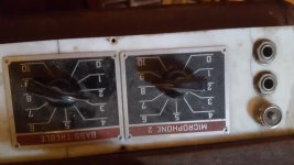
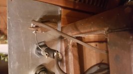
Ill attach pictures of the switch and fuse, and you can also see in the other picture where I cut the old wires off.
Currently the bottom of the fuse is wired to a power transformer black wire. The wire off the switch is wired to the tube, same spot the old wire was cut off.
Thanks for the help and sorry for the elementary wiring questions, I just want to make sure I get it right.
From what I understand, to be safe, I shouldn't just wire my new cord to where the old cord was, and just connect the green wire to the chassis. This is what I read:
"The fuse and the switch should be on the incoming hot wire and the neutral should go directly to the transformer. If you fuse the neutral and it blows you will still have 120v hot potentially thru the windings of the tranny. If you have the fuse on the hot lead when it blows there should be zero potential to ground in the amp. Much safer that way"
So just making sure I don't have this backward, because my the plugs on my original cord are the exact same size and I cant tell which is hot or neutral.
So is hot supposed to go to the transformer black wire, and neutral wired directly to the tube on my amp, or is it the other way around?
This is one persons advice:
"As has been mentioned, you want the fuse and switch to be in the AC hot side circuit. You will be wiring the AC cord hot wire to the end connector of the fuse post. The other lug of the fuse post will go to the AC switch. The existing PT primary connection on the other lug of the AC switch will remain as is.
The neutral wire from the cord will be butt-joined to the low side wire of the PT primary; properly heat shrinked for protection.
The capacitor on the fuse post to ground will be removed entirely.
The ground wire from the AC cord will need to be soldered to a star washer solder lug, and that lug installed on a bolt that makes good connection to the chassis. I'd recommend using the bolt that has the PT ground connections on it. DO NOT just strip the AC cord ground wire and schlepp it under a chassis bolt.
If you have any doubts about being able to do this correctly, take it to a good tech"
I'm sure I can do this correctly, with some help 🙂
So according to this, and if I have the polarity correct, I would attach my new hot black wire to the bottom of the fuse, which is connected to the black power transformer wire.
I'm not sure where to attach the white neutral wire though. Would it still just go directly to the tube like the old wire did?
Ill attach pictures of the switch and fuse, and you can also see in the other picture where I cut the old wires off.
Currently the bottom of the fuse is wired to a power transformer black wire. The wire off the switch is wired to the tube, same spot the old wire was cut off.
Thanks for the help and sorry for the elementary wiring questions, I just want to make sure I get it right.
Neutral does not go to a tube (unless this is transformerless, and it isn't).
If it looks like it does, look-up the tube pinout. Probably the line goes to an "unused" terminal--- it is a tie-point. That was often done but can go badly. Add a proper terminal.
Yes, *Green To Chassis*!
Black and white.... there's standards, but actually it should not matter. Fuse, switch, transformer, and back to the power company; any order works.
I just wired the 3 prong cord to where the old cord was connected and grounded to the chassis. I will wire it properly when I recap it.
Good news is my fuse holder came today and the amp actually works!
It barely worked at first but after cleaning the pots it came to life.
I'm pretty excited because it sounded great, even on my cheap guitar with old strings.
Wish I wouldn't have sold my PRS now lol.
Of course it blew the fuse after about 5 minutes of messing around with it. I wasn't using a slow blow fuse just a normal 1 amp I grabbed from the auto parts store so maybe that was it. Not terribly worried about it since it actually worked 🙂
Er .... not "100 ways" 😱 .... you quote two and both say the same 😉Wow, there a hundred different opinions on the internet on how to connect a 3 prong plug.
"The fuse and the switch should be on the incoming hot wire and the neutral should go directly to the transformer."
This is one persons advice:
"As has been mentioned, you want the fuse and switch to be in the AC hot side circuit. "
Ok so not 100 lol, but you can see my confusion.
A couple posts above I was told that the order doesn't matter and then I read that the hot side should go to the fuse and switch.
I'm going to go with it doesn't matter since the original plug could have been plugged in either way, without knowing if it was correct or not. If it's actually safer to run the hot side to the fuse and switch, then that is what I'll do.
It's debatable.
In the US, _I_ say there is a high chance the outlet is mis-wired. Any plan that *relies* on H and N being in the right place is doomed.
In Germany, there is no way to know which is H and N.
In some place in Argentina, there is no N (both are H).
It "does not matter" because it has a PLUG. If you are doing ANYthing around the line wiring, *UN-PLUG*!! In this case, this includes the FUSE, because that type fuseholder "can" give you a shock.
- Status
- Not open for further replies.
- Home
- Live Sound
- Instruments and Amps
- Help with unknown vintage amp