Hi All.
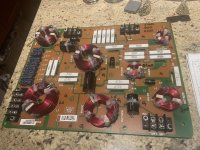
I picked up a stack of 3 way crossovers that were, according to the vendor at a local electronics surplus store, pulls from a theatre that had replaced its entire sound system. These crossovers have no documentation, and I don’t know what drivers they were used on or the impedance of those drivers. I used the parts from a few of these crossovers to build a couple of pairs of simple 12 DB per octave two way crossovers, but I have several left and would love to learn more about them as built and in their original form.
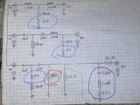
I have a attached a photo of the crossover, and of a schematic I made up by tracing the circuit. My questions are about the components in the crossover that I have circled and what purpose they serve…
1. What is the purpose of the resistors circled in blue? The two that are in between capacitors and ground? The one that is positioned in front of the .56mH inductor?
2. Does the 51 Ohm resistor circled in red work with the 10.1 Ohm resistor in series with the tweeter positive output as a voltage divider to reduce output?
3. What does the .51 mH inductor circled in green do?
4. Are the three components circled in purple a shaping circuit/EQ for the tweeter?
My apologies if these are newbie questions, and thanks in advance for your help
I picked up a stack of 3 way crossovers that were, according to the vendor at a local electronics surplus store, pulls from a theatre that had replaced its entire sound system. These crossovers have no documentation, and I don’t know what drivers they were used on or the impedance of those drivers. I used the parts from a few of these crossovers to build a couple of pairs of simple 12 DB per octave two way crossovers, but I have several left and would love to learn more about them as built and in their original form.
I have a attached a photo of the crossover, and of a schematic I made up by tracing the circuit. My questions are about the components in the crossover that I have circled and what purpose they serve…
1. What is the purpose of the resistors circled in blue? The two that are in between capacitors and ground? The one that is positioned in front of the .56mH inductor?
2. Does the 51 Ohm resistor circled in red work with the 10.1 Ohm resistor in series with the tweeter positive output as a voltage divider to reduce output?
3. What does the .51 mH inductor circled in green do?
4. Are the three components circled in purple a shaping circuit/EQ for the tweeter?
My apologies if these are newbie questions, and thanks in advance for your help
Attachments
That crossover is not so useful without the exact drivers used.
Blue stuff:
The .5 ohm in the LF section slightly lowers the resonance in the third order filter.
The 2 ohm in the MF section is part of a zobel with the capacitor to counter midrange driver inductance.
The 3 ohm in the HF section also slightly lowers the resonance of the circuit. Notice the filter sees a higher than 8 ohm impedance since there is a 10.1 ohm resistor in series with the tweeter.
The 51 ohm resistor in red slightly loads the filter. It is not really part of an L pad with the 10 ohm resistor.
The .51 mH inductor circled in green makes a 4th order filter instead of a third.
The components in purple are to counter some peak in the hf range. More likely to counter something around 3-8 Khz of the tweeter but that is just a guess.
Thanks for the reply and explanations.. Most.helpful! I ran the three outputs individually through a single full range 8 Ohm driver and measured the output with REW. Based upon the FR response, it appears that the original drivers were not all 8 ohm and not of equal sensitivity. I’m hoping someone will recognize these crossovers and have more info on their original use.That crossover is not so useful without the exact drivers used.
Blue stuff:
The .5 ohm in the LF section slightly lowers the resonance in the third order filter.
The 2 ohm in the MF section is part of a zobel with the capacitor to counter midrange driver inductance.
The 3 ohm in the HF section also slightly lowers the resonance of the circuit. Notice the filter sees a higher than 8 ohm impedance since there is a 10.1 ohm resistor in series with the tweeter.
The 51 ohm resistor in red slightly loads the filter. It is not really part of an L pad with the 10 ohm resistor.
The .51 mH inductor circled in green makes a 4th order filter instead of a third.
The components in purple are to counter some peak in the hf range. More likely to counter something around 3-8 Khz of the tweeter but that is just a guess.
probably best to use the parts for new builds; I find that usually re-using old systems is more time consuming than starting from scratch
I have already done so, but this is more of a learning exercise for me.probably best to use the parts for new builds; I find that usually re-using old systems is more time consuming than starting from scratch