Hi All,
I have recently started a project to build my own headphone amplifier from scratch. I like the sound of the resulting amplifier, but hearing some hum (initially but solved by reducing bias in the output stage) and a faint static like buzzing noise that does not change with turning the pot either way. I hope kind fellow members here can help to shed some light or provide suggestions to solve the buzzing noise.
The schematic of the power supply, voltage gain stage and output stage are as attached (all separate PCBs, 1 for voltage gain stage, 2 for left and right channels of the output stage.
1. Power supply: I figure it is easier to connect with all the connections located on the PCB, therefore included terminal blocks for AC input, power switch, transformer primary and secondary all onboard. The transformer voltage is 17-0-17. I have adjusted the trimpots so that the final DC output with no load is +-15V. The board has 3 output terminal blocks connected in parallel so that the voltage gain stage and the output stages all share a single power source.
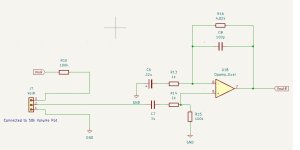
2. Voltage gain stage: since this is my first attempt at building a headphone amplifier, I am not sure what kind of voltage is required, therefore started with a gain of 5. The 100k resistor in front of the volume pot is to attenuate the signal since I find that the gain is a bit too much for my headphone.
3. Output stage: I have set the bias initially to 400mA per channel, and later reduced it to 200mA.
The problem: initial biasing and offset nulling went as planned. When I pluggged my headphones in, I initially hear both a low frequency hum + a static like buzzing noise.
What I have done so far: Initially I was suspecting a ground loop for the hum. However, when I measured the output voltage of the regulator with all boards connected, I find that the voltage has dropped from +-15V to +-14.2V. My guess is that the regulator chip I got is probably a fake one that does not meet the 1.5A specs. When I tried reducing the bias from 400mA per channel to 200mA per channel, the output voltage from the regulators went back to +-15V, and the hum disappeared. So setting the bias to 400mA might have exceeded the capability of the regulator and impacted the PSSR performance and let the noise from the unregulated supply come through. However, the static like buzzing still remains after the hum was gone. I have tried to turn the volume pot to minimum and maximum, and the buzzing noise does not change at all. My question: what could have caused the buzzing noise, and how to eliminate it? It is not loud. I can hear it when there's no music playing, and it will be masked at medium volume level, and I don't listen to music loudly with headphones. Any suggestions are appreciated!
Best regards
Roger
I have recently started a project to build my own headphone amplifier from scratch. I like the sound of the resulting amplifier, but hearing some hum (initially but solved by reducing bias in the output stage) and a faint static like buzzing noise that does not change with turning the pot either way. I hope kind fellow members here can help to shed some light or provide suggestions to solve the buzzing noise.
The schematic of the power supply, voltage gain stage and output stage are as attached (all separate PCBs, 1 for voltage gain stage, 2 for left and right channels of the output stage.
1. Power supply: I figure it is easier to connect with all the connections located on the PCB, therefore included terminal blocks for AC input, power switch, transformer primary and secondary all onboard. The transformer voltage is 17-0-17. I have adjusted the trimpots so that the final DC output with no load is +-15V. The board has 3 output terminal blocks connected in parallel so that the voltage gain stage and the output stages all share a single power source.
2. Voltage gain stage: since this is my first attempt at building a headphone amplifier, I am not sure what kind of voltage is required, therefore started with a gain of 5. The 100k resistor in front of the volume pot is to attenuate the signal since I find that the gain is a bit too much for my headphone.
3. Output stage: I have set the bias initially to 400mA per channel, and later reduced it to 200mA.
The problem: initial biasing and offset nulling went as planned. When I pluggged my headphones in, I initially hear both a low frequency hum + a static like buzzing noise.
What I have done so far: Initially I was suspecting a ground loop for the hum. However, when I measured the output voltage of the regulator with all boards connected, I find that the voltage has dropped from +-15V to +-14.2V. My guess is that the regulator chip I got is probably a fake one that does not meet the 1.5A specs. When I tried reducing the bias from 400mA per channel to 200mA per channel, the output voltage from the regulators went back to +-15V, and the hum disappeared. So setting the bias to 400mA might have exceeded the capability of the regulator and impacted the PSSR performance and let the noise from the unregulated supply come through. However, the static like buzzing still remains after the hum was gone. I have tried to turn the volume pot to minimum and maximum, and the buzzing noise does not change at all. My question: what could have caused the buzzing noise, and how to eliminate it? It is not loud. I can hear it when there's no music playing, and it will be masked at medium volume level, and I don't listen to music loudly with headphones. Any suggestions are appreciated!
Best regards
Roger
Attachments
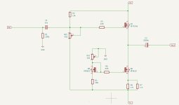

Hi. I see one problem with design. Ouput stage pics , resistor R2 (10k) , provides not only biasing of mosfet, but also supplies all kinda power supply noises from power supply to input. You should split this resistor in 2 pieces and put capacitor from middle to ground. This will filter some noise even if psu is unregulated or input voltage is sagged too much for regulars to operate . Lm317/337 needs few vokts headroom for operation, so for 15v ouput you need to have at least 17-18v dc input as minimum , including ripple voltage. If voltage is too low , regulator can't reduce ripple, and you need increase filter capacitors, increase transformers voltage, or replace regulators to low drop ones ,or discrete low drop design.
Hi ximikas,
Thanks for the suggestion. I have added the resistor and capacitor. Is this what you mean? Should I also do the same for the negative supply, i.e. RV1?
As for the headroom for LM317/337, yes I am aware of that. 17-0-17 transformer will give around +-24V DC unregulated, so I think this should be enough.
Attachments
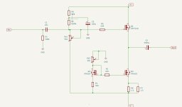
Yes, if you will add a resistor and capacitor in series with RV2 connection to gnd , it may improve additionally, but capacitor must be connected not to gnd, but to -15V, because current source is -15V refetenced. In positove supply you added exactly what i meant. Also, you are saying voltage is +-24V before regulators, but such voltage is only in condition with lower bias or no load at all? Hot much it sags when you set 400ma bias in both channels?
Right. Got you on the need to turn the capacitor around for the negative rail.
I forgot to measure the unregulated voltage when the bias was set to 400ma. However, I did measure the transformer output, and that was 16V-0-16V, so I assume the unregulated DC was +- 22.6V, and should still be sufficient for the regulators. However, the output from the regulators dropped to +-14.2V.
I forgot to measure the unregulated voltage when the bias was set to 400ma. However, I did measure the transformer output, and that was 16V-0-16V, so I assume the unregulated DC was +- 22.6V, and should still be sufficient for the regulators. However, the output from the regulators dropped to +-14.2V.
So , actually if regulators output dropped, that proves either ripple too high for current load amperage, or simply transformer is too weak to supply required current
Alright. I might verify whether the transformer is under sized if I can get my hands on a bigger one later in time. But for now I think 200mA is more than sufficient for my headphones. I am still suspecting that the regulator chips that I got are not the real deal, coz from the datasheet of LM317, it is capable of ripple rejection at an average of 60dB across current load of 0-1.5A and at frequency below 10khz.
I will include the filters in my next iteration of PCB. Thanks a lot for your help. I really appreciate it!
I will include the filters in my next iteration of PCB. Thanks a lot for your help. I really appreciate it!
Transformer is clearly undersized. If you run 400ma bias and 2 channels, it must be with at least 1,2-1,5 ampere rated secondary winding. Because idle current load will be always present, unlike audio signal load varies with signal.
You are right. My transformer is rated at 40VA, with 1.0A secondary winding. I will probably stick to this transformer at the moment, since 400mA bias is not required at this moment.
1,0Ampere should be enough, just margin is low and transformer may heat up over time. I see in your psu schematic CRC filter , with huge 2,2 ohm resistors, they will lose 4,4V in total, thats maybe problem. I doubt if that will make any noticable mprovement . Try to decrease each 2,2 ohm resistor to lets say 0,22-0,47 ohms and try 400ma bias .
OK. I will look out for the heating up of transformer.
As for the resistors, I chose 2.2 ohms because it will give a corner frequency of around 22 Hz. 0.47 ohms gives 103 Hz. Would it be effective in filtering the 50/60 Hz noise? Anyway, I will try it out and see whether there's any audible noise.
As for the resistors, I chose 2.2 ohms because it will give a corner frequency of around 22 Hz. 0.47 ohms gives 103 Hz. Would it be effective in filtering the 50/60 Hz noise? Anyway, I will try it out and see whether there's any audible noise.
50/60hz is ac coming from transformer, after diode bridge you will have 100/120hz ripple, also you have voltage regulators, so this crc filtering may be unnecessary at all I think. Any resistor will give improvement in filtering, if compare with shorting it . voltage loss is more important i think.
- Home
- Amplifiers
- Headphone Systems
- Help with troubleshooting faint buzzing noise from headphones