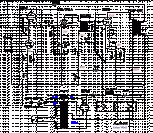
I'm going to make a new amp and use this schematic, but I don't understand one part. Right after the rectifier tube is an unmarked resistor. I thought the rectifier needed a cap first? If a resistor does make sense here, what value should I use?
Also, the pot on the 300b isn't labelled either. 100 ohm linear for that spot?
Also, the pot on the 300b isn't labelled either. 100 ohm linear for that spot?
Attachments
I would use 100k for input pot but put a 1meg to ground on grid to ground to stop dc scratching of the pot.
Valve rectification usually has a max value first cap which I think is usually about 47uf for that rectifier but check in spec. I dont think you need that first resistor as I have neve used it.
Valve rectification usually has a max value first cap which I think is usually about 47uf for that rectifier but check in spec. I dont think you need that first resistor as I have neve used it.
That resistor can reduce current charging pulses but with 10uF I think you can either leave it out or use it to trim for 420V at the final filter, neither here nor there.
If you're building new, consider a choke input instead.
Really nice circuit IMO, although you could configure the input as a differential pair and take output from one plate only and negate need for cathode bypass capacitor.
0.18uF and 47k is -3dB at 20Hz and SRPP likes a 'low' impedance so figure to increase the coupling capacitor value instead of increasing the grid leak value if wanting more LF, or less phase corruption at LF.
Be sure to try it without the 24k resistor across the NC20 transformer secondary.
As it is, nice design, 4mA through 6SN7 is going to give it some 'flavor', try it.. can always increase the current or change it around.
Last edited:
I don't know if a final decision has been made to use this design or whether that's also a matter for discussion. I've been building 300b amps for years and abandoned 3 stage designs a while ago. Here we have more gain than is needed in the front end including 2 cathode bypass caps, plus a feedback loop. This could be replaced by a single high gain tube with a mu of around 40 or maybe a bit more, with no global feedback. Plenty of designs use that configuration.
Lico,
This is a good design, value of pot can be anything 20k to 250k and unnamed power supply resistor is not important, as above.
Just build it, 6V6 driver gives a 'big sound'. I know because I have built just like this (but with common cathode input stage), otherwise much the same.
This is a good design, value of pot can be anything 20k to 250k and unnamed power supply resistor is not important, as above.
Just build it, 6V6 driver gives a 'big sound'. I know because I have built just like this (but with common cathode input stage), otherwise much the same.
- Home
- Amplifiers
- Tubes / Valves
- help with this 300b schematic
