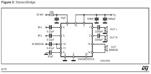
I tried to seach this forum for some improvements for the National's datasheet schematic for tda7375.
I tried the stereo/bridge schematic, but it gives me constant hum in "out L" and "out bridge". The "out R" is quite silent. I'm not using a custom pcb, the components are practically soldered to the pins straight. The vcc pin and the other input pin are next to each other, so can this cause the hum? Could I add somekind of additional filter to the input?
I know that a good pcb would be wise to use, but I don't have the possibility to make one.
Oh, and my psu is 12 volt trafo separate from the amp, so that can't cause the hum, or can it?
Attachments
Hi all!
I did some more reading and realized that the hum came from the psu, because my trafo gave 12 VAC out so I had added a bridge rectifier to it. Now I added two caps to the PSU and the amp runs nice and silent.
I'm trying to put the whole mess into a case so maybe you'll see it in the chipamp pics later.
Hello!
I've had this amp in use for a while, but I noticed that I still get some hum in other channel.
My amp is now in an ATX-psu case with the trafo, so it probably isn't the best option, but I still think that this amp could hum less. I'm going to make a proper PCB soon, but what other things could I do to reduce the hum?
Now I have one 4700uF and one 2200uF cap after the rectifier. What kind of caps do you suggest I could use in the rectifier itself, and will it reduce the hum?
hum with tda7375 amp
Hi,
I do not know if you wired correctly the ground, if not, you have to get 1 wire ground of each board and connect it at 1 point at the chassi of the amp. You have to insulate the RCAs from the chassi.
Hope this helps
Hi,
I do not know if you wired correctly the ground, if not, you have to get 1 wire ground of each board and connect it at 1 point at the chassi of the amp. You have to insulate the RCAs from the chassi.
Hope this helps
Where should I add the 220uF cap? As you can see, I have 1000uF and 100nF caps on the board and 4700uF and 2200uF in the voltage rail.
I'll also need to check the grounding, thanks!
Can a ground-problem create hum in one channel only? Because the other channel is totally hum-free.
I'll also need to check the grounding, thanks!
Can a ground-problem create hum in one channel only? Because the other channel is totally hum-free.
Hi all!
I've had this amp up and running for a while. I'm still having the hum-problem and no decent PCB. I also haven't got a decent low-pass filter done for the bridge channel, so I'm planning on modifying the amplifier to stereo.
I made a quick sketch about the PCB I was going to make. I also added the regulator to the board. It's there to limit the standby-pin voltage.
I didn't remember to display the component values, but I have 470n as input caps and 1000u and 100n in the supply rail.
So how does the PCB look like?
An externally hosted image should be here but it was not working when we last tested it.
eketehe said:Hv a 7812 or better regulator+ more 220uF before chips
Not with an amp chip that can quite easily draw more then 1 amp that a standard 3 pin regulator is limited to.
As for the hum, have you earthed BOTH pins on the chip? There is a SG earth and a PW earth, they should both be earthed together.
Go over your circuit and make sure it matches the one shown in the data sheet.
- Status
- Not open for further replies.
- Home
- Amplifiers
- Chip Amps
- Help with tda7375