I made my first DAC on breadboard and it don't work.
I made few changes, compared to attached schematic. I use CS8414, instead CS8412, with 2 x LM7805, one for digital part and one for analog. And i have simple wires in 22 ohm resistors place.
I try it with cheap DVD, in settings I try both SPDIF/PCM and SPDIF/RAW, no audio output in both.
I check all voltages on all power pins are correct, on AOR and AOL is about 5V, on VREF 2V, on BCK 4.9V, on WS sometimes 0, sometimes 2-3V, on DATA 0V. I disconnect 3 wires from CS to DAC and turn in, on all 3 DAC input pins - 1.2V, on CS output 0.
wen DAC is on some time, LM7808 and DAC chip are litle warm, 5V regulators is cold.
I check all solderings few times, all is correct. What can I check more?
Are CS8414 different from 8412?
Are 22ohm important? I see somewhere schem without it.
Maybe DVD have not digital signal at output?
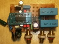
Attachments

Picture would help.
I made a TDA1543 DAC this week with Twisted Pear receiver and DAC on separate board. It did not work at first as there was no connection between the DAC ground and receiver ground as I used two supplies. After connecting the grounds I had music.
But again..... picture would help.
Good luck,
Jeroen
I made a TDA1543 DAC this week with Twisted Pear receiver and DAC on separate board. It did not work at first as there was no connection between the DAC ground and receiver ground as I used two supplies. After connecting the grounds I had music.
But again..... picture would help.
Good luck,
Jeroen
You need to add what is commonly known as an "idi0t light". It will light up when locked to the SPDIF signal.
grounding issue?
if ur voltage regulators are cold that means they are not working properly... if they are not grounded properly it probably just shoots out whatever input voltage as its output... are all ur components grounded properly?
if ur voltage regulators are cold that means they are not working properly... if they are not grounded properly it probably just shoots out whatever input voltage as its output... are all ur components grounded properly?
rfbrw, any link to this "idi0t light"? Are I understand right, it show me, are digital signal on DVD player or not.
BTW, which settings I need in DVD - spdif/pcm or spdif/raw ?
Are there way to now, are on receiver output signal - where is error, in CS or in DAC.
jayang727, I think all grounding is correct. I use 12V regulated PS, on pins 7, 22 and 24 I have 5V on DAC's pin 5 - 8V.
I check all voltages and ground on pins 8, 13, 17, 18, 21 and 23 before installing chips in sockets.
Zigis said:rfbrw, any link to this "idi0t light"? Are I understand right, it show me, are digital signal on DVD player or not.
BTW, which settings I need in DVD - spdif/pcm or spdif/raw ?
Are there way to now, are on receiver output signal - where is error, in CS or in DAC.
The CS8412/4 has two pins that go high in the event of an error. Pin 25, ERF will go high when there is an error. Pin 28 VERF will also go high in the event of an error but as it is logically OR'ed with the validity bit it will also go high if the data is not LPCM, i.e. AC3 data or MP3 data.
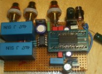
Attachments
8414 + 1543 works fine on my experiment.
I would recommend you should go for 8414 datasheet. There are some pins assigned to be a status pins. If you connect those pins with leds / resistors to ground, it will definately tells you what's going on at that moment. Maybe even the signal type/sampling rate. 😉
I would recommend you should go for 8414 datasheet. There are some pins assigned to be a status pins. If you connect those pins with leds / resistors to ground, it will definately tells you what's going on at that moment. Maybe even the signal type/sampling rate. 😉
Thanks, rfbrw, for the schematic, I made it, red LED work (28 to ground), green not work (25 to +5) all the way.
Archwn, do you mean pins 1-6 ?
I have 0V on pin 1 and +5V on pins 2, 3, 4, 5, 6, 24, 25, 27, 28.
I am going to reed datasheet, all thees digital stuff is dark wood for me.
Do I need spdif/pcm or spdif/raw on player output, and what is the difference?
Archwn, do you mean pins 1-6 ?
I have 0V on pin 1 and +5V on pins 2, 3, 4, 5, 6, 24, 25, 27, 28.
I am going to reed datasheet, all thees digital stuff is dark wood for me.
Do I need spdif/pcm or spdif/raw on player output, and what is the difference?
Zigis said:Thanks, rfbrw, for the schematic, I made it, red LED work (28 to ground), green not work (25 to +5) all the way.
There is a signal integrity error. The voltage level is too low or something is connected to ground that shouldn't be or there is a short somewhere.
I found one error, pins 13 and 14 was short on adapter.
I fix it, now on 27 is 0 (+5 before)`, on 4,5,6- 5V all way, on 2 and 3 sometime 0, sometime +5
I have adapter on socket, maybe I can try to resolder adapter direct to board yesterday.
In working receiver what voltage must be on pins 1-6 with signal in and what without signal ?
I fix it, now on 27 is 0 (+5 before)`, on 4,5,6- 5V all way, on 2 and 3 sometime 0, sometime +5
I have adapter on socket, maybe I can try to resolder adapter direct to board yesterday.
In working receiver what voltage must be on pins 1-6 with signal in and what without signal ?
OK, I read datasheet and I understand that E2, E1 and E0 +5 are "no lock" error - PLL is not locked onto the incoming data stream, whatever this mean.
I resolder filter from schematic in post 1 to datasheet standard 470 ohm/0.068mf directly to adapter and both power supples decoupling 10mf on adapter too.
What can I do next I really don't no.
I resolder filter from schematic in post 1 to datasheet standard 470 ohm/0.068mf directly to adapter and both power supples decoupling 10mf on adapter too.
What can I do next I really don't no.
Forget about pins 1 to 6. Unless you are using a 6.144MHz reference signal on the FCK input and are then able to decode the resulting data or have a thorough understanding of the use of subcode in the IEC60958 standard, they will mean nothing to you. Pins 25 and 28 will tell you all you need to know.
Do you have another SPDIF source?
Do you have another SPDIF source?
- Status
- Not open for further replies.
- Home
- Source & Line
- Digital Source
- Help with TDA1543 DAC !