Hi CivicProtection,
Yes, the RH84 is popular, and very much appreciated, at least by me.
So much, I actually build two versions of it;
the first being my very first amplifier build; keeping it open for experimenting,
the second in a nice case (re-use of a relais housing from army surplus).
I've build a whole lot of amplifiers since, but I still use the second RH84 daily.
Look around these pages for the various comments on the RH84SE.
Please note that however lots of people use this design as a First Build,
there are quite some experienced builders who build it and even they like it.
Don't worry about the tube-rectifier on the original schematic,
In my first build I used a diode-bridge, in my second I used a tube.
There's a difference in sonics but both sound absolutely fine to me.
But be sure to have a sturdy PSU with minimal ripple.
It may not show on normal speakers, but when you want to use it as
a headphone amp aswell..... You'll hear every tiny bit of ripple.
This goes for any SE amplifier really, wether you choose RH84 or not
My advice: Walk the RH84 road !
Nice looking builds you made there mate! I think I have gathered enough to give this design a "green light". I was worried about the power supply section, but I read here somewhere that some of the new zener diods can work without hum?
And thanks folks for finding strictly 220v versions of the circuits you showed me.
Saved me trouble. Much appreciated!
Saved me trouble. Much appreciated!
I read here somewhere that some of the new zener diods can work without hum?
Zener diodes are used for voltage references not rectifiers. Hum has nothing to do with zener diodes.
All that matters for the supply section is the output voltage and the supply ripple. The ripple is an AC component than "rides" on the DC output voltage. It's the amount of AC that makes it past the filter cap. The ripple is a function of the capacity of the capacitor and the current draw of the load. There are various techniques for reducing supply ripple. A voltage regulator, RC, LC filtering to name a few. You can also just increase the size (capacity) of the cap. With tube rectifiers there are limits to how much cap you can use (see the tube datasheets). Semiconductor diodes are much more forgiving and allow for 1000's of uF caps.
As far as 120 vs 230 V input to the supply goes. Doesn't matter. As long as the secondary voltage of the transformer you use is roughly the same (say within 10 % of the target voltage) you'll be fine.
Another source of hum is poor layout -- especially poor grounding. Look up "star grounding" and do some reading. Topic for another day...
~Tom

Philips reel-to-reel schematics
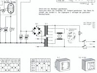
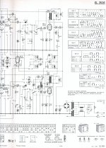
Here are some schematics to show the wiring for the power and output transformers from the reel-to-reel tape recorder. It's very good iron although the power transformer has no 5v winding for a rectifier (original used diodes). The output transformers are VERY respectable 5K:4 ohm units; I'm listening to a pair now in an RH84 which I would also highly recommend morphing your parts into.
Enjoy,
Brian
Attachments
- Status
- Not open for further replies.