Hello all! I'm a beginner, bit off a little too much. I removed the amplifier guts from an old 1961 Phillips reel-to-reel tape recorder. I hacked the wires and now I have three sub assemblies.
Long story short: I have no use for an old tape machine, I am on my way home in a month, can't take the heavy ***** with me, and all I want is to have a tubey headphone amplifier for my notebook with perhaps output for small speakers. And not see an antique go completely in the rubish bin.
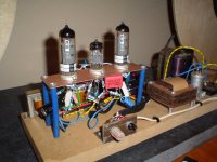
Now after disengaging the amp circuits from the tape mechanism, I now have a bunch of hacked wires, daughterboards with big hairy iron transformers, tube sockets, old caps, and audio pots and connectors.
I just made a pile of crap. Some of the circuitry is now not needed, IE circuit to controll volume level tube, junk for the recording/ playback head, selector between PA input/mono/stereo radio. Many tape functions now obsolite.
I have no idea how to make all the sub-asemblies fit back together
and eliminate the unessesary circuits.
I do know I have a surplus of good valuable components to design a new amplifier (and better) stereo amp.
What I want is a tube stereo amp for headphones with jacks for speakers.
I have the headphone jacks that swich off sound to speakers.
I will document everything better for you folks later, but for now
I will give a list of what I can see:
-big power transformer (110-220)
-two big (why so big?) output transformers. Not sure IF they are outputs but what else could they be?
-tube sockets
-Mono audio sockets, stereo audio socket.
-pots dual and single
-nuts bolts
-old wiring still (felxable) power cord
-rotten old caps, and resistors
-Tubes:
2x ecc83 12ax7
2x ef86 6267
2x el84 6bq5
Thankyou so much for any kind of designs or help of any kind, I'm excited to get started. I am hoping I can make something with what I just pulled apart.
Long story short: I have no use for an old tape machine, I am on my way home in a month, can't take the heavy ***** with me, and all I want is to have a tubey headphone amplifier for my notebook with perhaps output for small speakers. And not see an antique go completely in the rubish bin.
Now after disengaging the amp circuits from the tape mechanism, I now have a bunch of hacked wires, daughterboards with big hairy iron transformers, tube sockets, old caps, and audio pots and connectors.
I just made a pile of crap. Some of the circuitry is now not needed, IE circuit to controll volume level tube, junk for the recording/ playback head, selector between PA input/mono/stereo radio. Many tape functions now obsolite.
I have no idea how to make all the sub-asemblies fit back together
and eliminate the unessesary circuits.
I do know I have a surplus of good valuable components to design a new amplifier (and better) stereo amp.
What I want is a tube stereo amp for headphones with jacks for speakers.
I have the headphone jacks that swich off sound to speakers.
I will document everything better for you folks later, but for now
I will give a list of what I can see:
-big power transformer (110-220)
-two big (why so big?) output transformers. Not sure IF they are outputs but what else could they be?
-tube sockets
-Mono audio sockets, stereo audio socket.
-pots dual and single
-nuts bolts
-old wiring still (felxable) power cord
-rotten old caps, and resistors
-Tubes:
2x ecc83 12ax7
2x ef86 6267
2x el84 6bq5
Thankyou so much for any kind of designs or help of any kind, I'm excited to get started. I am hoping I can make something with what I just pulled apart.
Hello,
Save those resistors! They are probably carbon compostion type
like allen bradleys.😛 Good sounding.You can use those pcbs with the tubes
but you have to check what tubes they are by their numbers or letters
printed on the glass.Then knowing what tubes, you can find a headphone amp circuit that use them or similar tubes and start from there but most likely
you may have to change some of the connections on the pcb in order to use them in a amplifier circuit.Should not be too difficult.As for the transformers
if there are markings as to their voltages so much the better if not you will
have to power them and check with a multimeter but be careful as high voltages (DANGER)
are involved.Safety first!
regards.
Last edited:
I'd recommend tracing the schematic from the boards you have there. The tube complements and circuits themselves will show what each part's function was/is.
Then, you could consider just using the original output topology (which is single ended, assuming it was a stereo amplifier). The original probably uses the EL84's in pentode mode, which you could consider changing to triode mode. As you're aiming for a headphone amp, the power loss is not really a problem. Impedance mismatching, however, may be an issue, but again, this will mostly result in further power loss. Suppose you end up with a power output of say 500mW (sort of a worst case scenario), you'll still have ample power to drive any mid-range set of headphones.
Preamp stage topology will probably be a bit different from the original Philips stuff, since you're going to get rid of some functionality. You might only need one 12ax7 for both channels if you don't need any tone control or mixing capability.
There's dozens of schematics out there describing single ended EL84/other pentode amps, either or not in triode mode, and thousands of little triode preamp stage circuits. You will have to match them, which will involve some experimentation. Do you have the time for that? If not, then opt for something ready-made. Google turns out this one for example: Free Schematic Diagram at www.circuitdiagram.net
But there's lots more out there.
EL84 single-ended output stage driven by either the EF86 or ECC83. That would be my starting point with that tube collection. Something along the lines of the Tubelab Simple SE.
~Tom
~Tom
Sorry it was super late when I wrote all this.
Here is a revised parts list of the components I seperated this morning, and baggied up:
Tubes:
2x EL84 6BQ5
3x ECC83 12AX7
2x EF86 6267
Controls:
1x 200k (double ganged)
3x 500k (double ganged)
1x 200k (double but seperate knobs on one shaft)
Transformers:
2x output transformers: 291 WT 511 22
1x Power transformer: 301 WT 511 121
Rectifier: solid state 2 amp bridge rectifier SR-250. (small flat metal box)
Misc:
Mono audio input sockets, stereo headphone jack with internal insert cutoff switch.
Resistors, lots of bad caps. Still good 1961 era power wire, audio coax, low voltage wire, wall supplu wire and plug.
8x tube sockets. Yes you counted 7 tubes in my list, but there is a magic eye tube, but I won't be using it.
I'd like to use up all the tubes and components if possible, I want to make the most of it.
Unfortunatly the transformers are "un capped" and all connections are exposed. So I guess I won't be bolting to the top of a box and showing it off along with the tubes.
Need a nice stirdy box to house all this in, possibly house it all in a metal project box with a vent to cool and show off the glow. Interestingly I also have the small electric moroe that was just for blowing air arounf the larger tape player case. Use it here too? Man that is one nice quality motor.
Last edited:
I wouldn't use a fan in an audio amp. The fan itself makes noise (both acoustic and electronic) and moving air is not a quiet process.
You may not be able to safely expose the trafos on the top of the chassis, but you could still have the tubes topside. You could also build a small enclosure for the trafos. Along these lines.
Keep the magic eye tube. Those things are expensive...
Google "EL84 amplifier". I'm sure you'll find a schematic. Or search this forum. I linked to a schematic in my earlier post...
~Tom
Thank you all for the help and advice. I certainly appreciate it all!
This is still a live project so I'm still open to anything you have to suggest/advise. My time limit is Feb 1. I am settling on the design suggested earlier:
Free Schematic Diagram at www.circuitdiagram.net
I had hoped to fill this baby with all the tubes I got but four (2 per channel) should be good.
I am exploring the possibility of using an ATX power supply,not the standard one, one of the longer ATX kind, a dead (power user type). Initially I was hoping to use one of the ugly grey breaker box or junction boxes from home depot, and spraying it orange. Nounting everything inside, tubes, everything. The 12v fan is brushless and run at 6.3v rectified from the transformer. It wouldn't produce the noise as explained to me earlier with the AC motor type fan. Containing all this in the box will save it from getting smashed to hell on my way back home. But I will entertain other box construction options. ATX power supply is one thing, but I think I might spend the dollars and get a convention grey metal project box.
As I said; I am settling on the circuit mentined before, but what should it sound like with my nice heavy, good quality transformers and tubes? What is this single ended thing?
At the moment I am trying to figure what all the posts mean on the audio output transformers. I know which wire on the power transformer are the heater wires.
But I don't want to break nothing.
What is this single ended thing?
It's the topology of the output stage, either single ended (one output tube per channel) or push pull (two output tubes per channel).
Single ended output requires different output transformers than push pull, and from the info you have provided so far, the assumption is that your transformers are single ended.
Since you harvested two EL84s, There are two possibilities for the tape machine; it was either a push-pull mono topology, or a single ended stereo topology.
How many wires were connected to the output transformers? Was the tape recorder stereo or mono?
BW, the bill of materials provided early in the thread says 2X O/P trafos. Combine that with 2X EL84s and SE stereo is what you get.
SE pentode EL84s are good for roughly 5 WPC. Triode wiring the EL84s drops that to 2 or so WPC, BUT allows the use of extremely simple, no NFB, circuitry, ala the DECWARE SE84. The SE84 is good sounding and (IMO/IME) well worth "cloning". A single 12AV7 or 5965 works quite well in that circuit style. Save the 12AX7s and EF86s for another project, perhaps a phono preamp.
CP, DC fans generate more "hash" than AC fans. It's a matter of commutation, mechanical or electrical. Some strategically placed openings that allow for convection cooling are (IMO) your best bet.
Given its age, the salvaged bridge rectifier will be very noisy, due to large reverse recovery spikes. A set of 4X low noise UF4007s are an inexpensive replacement that's indicated.
It's the topology of the output stage, either single ended (one output tube per channel) or push pull (two output tubes per channel).
Single ended output requires different output transformers than push pull, and from the info you have provided so far, the assumption is that your transformers are single ended.
Since you harvested two EL84s, There are two possibilities for the tape machine; it was either a push-pull mono topology, or a single ended stereo topology.
How many wires were connected to the output transformers? Was the tape recorder stereo or mono?
I see a "stereo" written all over the place, like "Stereo headphone".
The tape recorder was "high fidelity".
BW, the bill of materials provided early in the thread says 2X O/P trafos. Combine that with 2X EL84s and SE stereo is what you get.
SE pentode EL84s are good for roughly 5 WPC. Triode wiring the EL84s drops that to 2 or so WPC, BUT allows the use of extremely simple, no NFB, circuitry, ala the DECWARE SE84. The SE84 is good sounding and (IMO/IME) well worth "cloning". A single 12AV7 or 5965 works quite well in that circuit style. Save the 12AX7s and EF86s for another project, perhaps a phono preamp.
CP, DC fans generate more "hash" than AC fans. It's a matter of commutation, mechanical or electrical. Some strategically placed openings that allow for convection cooling are (IMO) your best bet.
Given its age, the salvaged bridge rectifier will be very noisy, due to large reverse recovery spikes. A set of 4X low noise UF4007s are an inexpensive replacement that's indicated.
OK that cuts it: no fan. Vents will do for me.
i agree the rectifier is rotten, four 4007's would outperform the old replacment. The schematic I was shown, is no good?
Free Schematic Diagram at www.circuitdiagram.net
I have no interest in phono anything. All my music, all 1.1 TB of it is on my externall HD.
If all goes well I might give this as a birthday give to a loved one back home, right on time
Is this another homework assignment?
Naaw man, I have to return back home. Save up then visit this side of the pond again some other time.
The schematic I was shown, is no good?
Notice the triode/pentode switch. The 12AX7 simply lacks the cojones to drive a triode's CMiller. A pentode in the O/P position needs help from loop NFB, in order to obtain a satisfactory damping factor. That design SUCKS!
Do what's necessary to acquire EFFICIENT speakers. Then, a no NFB triode setup will work well. "Borrow" from the DECWARE SE84. You will get a little more gain from the 12AV7 or 5965 I previously mentioned than the μ 33 tubes Steve Deckert shows. That little extra can be very handy. The SV83, AKA EL84N, shown is really 6Π15Π (6p15p). If you set the sockets up for the 6Π15Π, both that type and the EL84/6BQ5 will function properly. Soviet era 6Π15Π-EV stock sounds NICE and would make for good replacements, after the EL84s you have wear out.
The schematic I was shown, is no good?
Free Schematic Diagram at www.circuitdiagram.net
It's probably a fine guitar amp. It's bandwidth will be about 200 Hz to whatever the OPT cuts out at. Not exactly suited for HiFi. I don't like the DC coupled input. I also don't like having the volume pot between two stages. I don't like a volume pot with no added resistance from the wiper to ground. Pots generally fail with the wiper open. This failure mode would wreak havoc on the circuit as is.
Did you look at the RH84 I linked to earlier at all? Lots of people on this forum have built these amps. They seem tried and true.
If you are dead set on using the guitar amp schematic you found for HiFi, I'd at least move the volume pot to the front, AC couple the input, change the cathode cap on the input tube to at least 10 uF (or use LED bias), increase the coupling cap to 220 nF, and increase the cathode bypass cap on the EL84 to 1000 uF.
If your intent is to use it as a guitar amp, just build it as-is. I'd still AC couple on the input, though.
~Tom
I'm still in the plan stage. I haven't zeroed in on anything yet as a final design.
I did look at the design you pointed out, I like it, it looks good!
Forget the guitar amp junker. Tell me more about:
RH 84 - Tube Audio ...... RH DESIGN
It is popular, and well appreciated here?
Hi CivicProtection,
Yes, the RH84 is popular, and very much appreciated, at least by me.
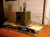
So much, I actually build two versions of it;
the first being my very first amplifier build; keeping it open for experimenting,
the second in a nice case (re-use of a relais housing from army surplus).
I've build a whole lot of amplifiers since, but I still use the second RH84 daily.
Look around these pages for the various comments on the RH84SE.
Please note that however lots of people use this design as a First Build,
there are quite some experienced builders who build it and even they like it.
Don't worry about the tube-rectifier on the original schematic,
In my first build I used a diode-bridge, in my second I used a tube.
There's a difference in sonics but both sound absolutely fine to me.
But be sure to have a sturdy PSU with minimal ripple.
It may not show on normal speakers, but when you want to use it as
a headphone amp aswell..... You'll hear every tiny bit of ripple.
This goes for any SE amplifier really, wether you choose RH84 or not
My advice: Walk the RH84 road !
Yes, the RH84 is popular, and very much appreciated, at least by me.
So much, I actually build two versions of it;
the first being my very first amplifier build; keeping it open for experimenting,
the second in a nice case (re-use of a relais housing from army surplus).
I've build a whole lot of amplifiers since, but I still use the second RH84 daily.
Look around these pages for the various comments on the RH84SE.
Please note that however lots of people use this design as a First Build,
there are quite some experienced builders who build it and even they like it.
Don't worry about the tube-rectifier on the original schematic,
In my first build I used a diode-bridge, in my second I used a tube.
There's a difference in sonics but both sound absolutely fine to me.
But be sure to have a sturdy PSU with minimal ripple.
It may not show on normal speakers, but when you want to use it as
a headphone amp aswell..... You'll hear every tiny bit of ripple.
This goes for any SE amplifier really, wether you choose RH84 or not
My advice: Walk the RH84 road !
Attachments
Sorry for the question about homework, but we do get some lazy dishonest students who pop up here and ask us to do their work for them. Some of them are quite open about their cheating, but others try to hide it at first.
I hope it goes well.
I hope it goes well.
Sorry for the question about homework, but we do get some lazy dishonest students who pop up here and ask us to do their work for them. Some of them are quite open about their cheating, but others try to hide it at first.
I hope it goes well.
No problem. Yes some lazy students DO actually waste 90% of their assignment time screwing around. Then at the last minute try to "pump" the forum members for information. And then use the plagorised information to try and pull their own chestnuts out of the fire in time. It doesn't work.
Thanks, I hope so too. Learning every minute of tinkering!
Last edited:
- Status
- Not open for further replies.
- Home
- Amplifiers
- Tubes / Valves
- Help with stereo tube amp design from parts