HiFi Loudspeaker Design
I plugged in your resistor values
If we assume the impedance is 6.6 Ohms, your L-pad would give -3 dB.
Since these are smaller speakers; higher power resistors most likely would not be necessary here.
if you use this calculator and assume 6.6 Ohms as I did, for an attenuation of only 1.5 dB, the series resistor would need to be 1 Ohm and the resistor across the driver would need to be 35 Ohm.
You can lift one lead of the 16 Ohm resistor and short across the series resistors; this would increase the level 3 dB. If you do this; make sure the volume control is set fairly low at first just to be safe.
so remove the 2.2uf altogether???and just pad it 1.5db???
what is the actual impedance at that frequency...or am i overthinking this...
what is the actual impedance at that frequency...or am i overthinking this...
I would leave the 2.2 uF and it's resistor in that circuit as is; it is a Zobel circuit most likely used to flatten the impedance curve so the 5.1 uF determines the crossover frequency alone.
HiFi Loudspeaker Design
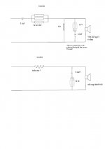
Zobel calculator and circuit description
Without trying to look up the driver specs; I assumed a DCR of 5 Ohms and inductance of 0.86 mH; this would give you the 2.2 uF and the combined resistance would be 6.25 Ohms. This is just an educated guess though. If you want to keep the crossover frequency the same; just adjust the resistor values per my post 21. You could upgrade the capacitor but try the resistor adjustments as my first suggestion. After that, upgrading to a better capacitor should give you more resolution and detail than a very cheap cap.
HiFi Loudspeaker Design
Zobel calculator and circuit description
Without trying to look up the driver specs; I assumed a DCR of 5 Ohms and inductance of 0.86 mH; this would give you the 2.2 uF and the combined resistance would be 6.25 Ohms. This is just an educated guess though. If you want to keep the crossover frequency the same; just adjust the resistor values per my post 21. You could upgrade the capacitor but try the resistor adjustments as my first suggestion. After that, upgrading to a better capacitor should give you more resolution and detail than a very cheap cap.
That is very good advice and easy to do - effectively removing the tweeter attenuation resistors from the circuit.You can lift one lead of the 16 Ohm resistor and short across the series resistors; this would increase the level 3 dB.
P.S. 16 Ohm should read 6 Ohm, of course.
That's OK. I should have paid more attention to oldspkrguy's calculations before putting my foot in it! 
Well the math works if you assume 6.6 Ohms instead of 6.0 Ohms for the driver. Zobel calculators give different results for C and R values so 6.6 Ohms is a reasonable thing for using the L-pad attenuation calculator. MOST OEM specs show Le at 1 KHz only; I have a LCR meter but it only measures L and C at 100 Hz. I use the impedance curves and not the stated static impedance to calculate all of my X/O values. I wish they would give us Le at 100 Hz, 1 KHz and 10 KHz all THREE!!! Then, we would have a better idea of the complex impedance.
Voltage divider - loaded and open-circuit dB calculator damping volts potentiometer circuit impedance damping pad decibel dB voltage attenuator impedance bridging matching - sengpielaudio Sengpiel Berlin
Another handy calculator for voltage divider plus dB attenuation. You can vary the attenuation resistor values but also the load resistor value.
Another handy calculator for voltage divider plus dB attenuation. You can vary the attenuation resistor values but also the load resistor value.
for the other calculator; I plugged in these values...Z1 = 2 Ohms, Z2 = 16 Ohms, Zload = 6.6 Ohms. I just set the input voltage = 1.00 Volt. Then click on Zload; then V out = 0.700...put 0.7 Volts in the numerator on the next formula and 1.0 Volt in the denominator. Click the equal sign; the result is about -3.1 dB. Now, if you want; you can plug in many different values for Z1, Z2 and Zload.
Blocked
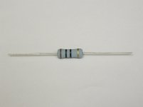
red, green, black, gold would be 25 Ohms, 5%. 3 in parallel would be 25/3 = 8.33 Ohms
Are these carbon resistors??? Metal film and higher quality non-inductive resistors for crossover use usually do NOT have a color code and usually have the value printed directly on the resistor body but it may be a short form code of some kind (varies by country, manufacture, etc.)...
probably carbon, but that's good because at least they are probably not the wire wound type that have inductance. And, in that circuit it's not as important as in the L-Pad attenuator circuit. In the L-Pad, higher quality resistors can definitely improve the sound quality (all else being equal of course)
I plugged in different values for Z1, Z2 and Zload and found that 4, 32 and 8 ohm gave -4.2 dB.for the other calculator; I plugged in these values...Now, if you want; you can plug in many different values for Z1, Z2 and Zload.
I then went back to the L-pad calculator and plugged in 8 ohm and 4.2dB. This gave Z1 (series) = 3 ohm and Z2 (shunt) = 13 ohm (figures rounded).
We now have two sets of resistor values for the same speaker impedance and attenuation - which is correct?
Now, for an L-Pad, the parallel combination of shunt resistance and speaker impedance, when added to the series resistance, must equal the speaker impedance.
Comparing the two sets of figures
32//8 + 4 = 6.4 + 4 = 10.4 ohm
13//8 + 3 = 5 + 3 = 8 ohm.
The latter set of figures satisfies the requirements for an L-pad, but the former does not.
Have I simply lost myself in a circular argument or is the 'voltage divider' calculator unsuited to the task? 😕
Just waking up, yes, I forgot about some of the lower Wattage film resistors using color code bands. The voltage divider calculator is universal; the L-Pad calculator specifically is designed so that the crossover components, amplifier, etc see the same impedance regardless of attenuation.
https://www.electronics-tutorials.ws/attenuators/l-pad-attenuator.html
handy explanations
I'll look more closely at the calculations once I get some coffee in me and my brain wakes up (the dog got me up at 2 AM to go outside so my sleep was interrupted; not a good thing for an old guy like me ha ha ha)
- Home
- Loudspeakers
- Multi-Way
- Help with speaker crossover