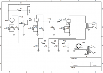
Already for weeks I have been trying to build my first SE tube amp from old soviet TV parts. Tubes are 6P14P on amp and 6N2P on preamp. The amp is working only if I play super mildly and on low level. As soon as I pluck some string heavier a horrible distortion starts. I think I have tried everything - different resistor values, different OPT, different input and pot wiring. Gods are against me! Is there a mistake in schematic? Are the tubes bad? (I have few, all second hand, but from different sources so some of them have to be good.) Probably its just me, but where? Power transformer is 216 Vac on secondaries. B+ is 295 Vdc, B+1 after OPT 260 Vdc, B+ 260Vdc, B+3 = 130 Vdc, B+4= 150 Vdc. Filament Voltage 6.8 V. I have two OPT - one from same TV (measures 485 ohms on primaries, 2,8 ohms secondaries (so WR should be 13:1?)), other one from old radio (WR 23:1).
(The value of R14 is 200 K right now and input has 1 meg resistor that's not shown in schematic).
Can someone help? Thanks in advance.
(The value of R14 is 200 K right now and input has 1 meg resistor that's not shown in schematic).
Can someone help? Thanks in advance.
Attachments
When you say "play" and "string" I assume you mean electric guitar? With the guitar volume pot wide open, perhaps one of those string strikes is putting volts of signal level into your amp's input (with modern pickups).
Do you have access to a sampling oscilloscope to verify this? Connect it to your guitar, strike the strings in the same way as that which causes your amp to distort and see what the peak and decaying voltage level actually is.
Once that is known, take a signal generator, set its output signal level in that ballpark, connect it to your amp and see if the 1st stage is clipping. If so, reduce gain until it can handle that level without large distortion. One way to reduce gain is to remove the cathode bypass cap there...
Distortion from rest of the amp is protected by the volume control between tube stage 1 and 2. As long as there's no distortion coming from stage 1, you can adjust for no distortion from the rest of the amp. The output sound level in that case is what it is.
If you want it to go apparently louder w/o distorting, put a compressor between your instrument and the amp and dial that in so as not to exceed the signal level distorting the 1st tube stage. You'll lose some dynamics when chunking on the strings, but it'll seem louder as a trade off.
I'm guessing the undistorted power output is a couple / few watts. How efficient is your speaker? Having a really efficient speaker will go a long way toward getting some SPL w/o distorting the amp -
What are the voltages on the grid, plate and cathodes?
Hi, on amp stage - plate 270 V, after OPT - 260 V, second grid - 232 V, cathode - 6 V. On preamp stage - 1st triode plate 142.5 V - 152.5 V (depending on volume), cathode - 0.5 V, 2nd triode - plate 123.5 V - 125 V, cathode - 0.65 V
When you say "play" and "string" I assume you mean electric guitar? With the guitar volume pot wide open, perhaps one of those string strikes is putting volts of signal level into your amp's input (with modern pickups).
Do you have access to a sampling oscilloscope to verify this? Connect it to your guitar, strike the strings in the same way as that which causes your amp to distort and see what the peak and decaying voltage level actually is.
Once that is known, take a signal generator, set its output signal level in that ballpark, connect it to your amp and see if the 1st stage is clipping. If so, reduce gain until it can handle that level without large distortion. One way to reduce gain is to remove the cathode bypass cap there...
Distortion from rest of the amp is protected by the volume control between tube stage 1 and 2. As long as there's no distortion coming from stage 1, you can adjust for no distortion from the rest of the amp. The output sound level in that case is what it is.
If you want it to go apparently louder w/o distorting, put a compressor between your instrument and the amp and dial that in so as not to exceed the signal level distorting the 1st tube stage. You'll lose some dynamics when chunking on the strings, but it'll seem louder as a trade off.
I'm guessing the undistorted power output is a couple / few watts. How efficient is your speaker? Having a really efficient speaker will go a long way toward getting some SPL w/o distorting the amp -
Hi, yes, I mean guitar. Unfortunately I don't have an oscilloscope. The amp should be 4 watts maximum. It's connected to 16 ohm speaker, not sure about efficiency, it is from bass guitar amp, I tried connecting 8 ohm speaker and it gets worse.
(The value of R14 is 200 K right now and input has 1 meg resistor that's not shown in schematic).
R14=200K is too much for the grid stopper resistor. Put some like 1K to 2K
it is good to have grid resistor at the input without that R, like in the schematic, not good at all...
The biasing values are incorrect in the first 2 tubes. You have negative grid bias about 0.5V at first and 0.65 in second. I think that Pick-up have high output levels. That signal is already greater than this 0.5V at the fist tube. Then amplified is even bigger coming to second tube. Double and very high unwanted distortion even with small input levels...
6N2P tube is equivalent of 12AX7 or ECC83. It has mju=100 (amplification factor). And You have 2 stages...
Output tube is if I am remeber well equivalent of EL84 tube?
Negative grid bias should be higher too. Try to get to -7V.
That 7V means that with this level of input signal AT the powr stage, output tube, You will have maximum power.
So You need only 3 to 6 times amplification before output stage to reach almost full power.
Input section is over-amplifying and putting in enormous distortion, cutting out the peaks of the signal amplitudes...
1. Eliminate one of the input tubes
2. Choose input tube with small amplification factor, put negative grid bias of the input tube like 2V or more. (Like ECC82)
3. Make a bit higher bias of output tube like -7V, by increasing value of R in katode.
4. The values of coupling C are wrong and with that resistors following, You will have NO low end...
Anyway another example of bad schematic picked up somewhere on the internat... 🙁 sorry
Last edited:
I agree with Zoran. My recommendations:
R8 and R10 should be about 1K.
Remove C9 and C7.
C6 and C8 should be at least 0.05
R6 can go as high as 300K safely.
R5 and R14 should be in the 300 to 1K range. Also add a 1K at the grid of the first pin.
C5 may optionally be removed if there is still too much gain. Or the pentode could be "triode strapped" (connect g2 to the anode instead of B2) for less gain.
That's about as much Muntzing as we can do.
Another idea could be to turn the first valve into a cathode follower. Remove C9, keep C7, move C8 to the cathode and remove R9. The advantage is you don't have too much gain and the first tube buffers the output of the guitar. Lower Miller effect might give a little better top end.
plate 270 V, after OPT - 260 V, second grid - 232 V, cathode - 6 V.
On preamp stage - 1st triode plate
142.5 V - 152.5 V (depending on volume), cathode - 0.5 V,
2nd triode - plate
123.5 V - 125 V, cathode - 0.65 V
Your cathode voltages on the preamp tube is too low, you have little room for the signal and it distorts.
R14, does not make much difference until the grid gets to 0V. The grid is a very high impedance and little current flows so the grid stopper does not develop much voltage across it. 1k will do nothing before a preamp triode. When you get to 0V that changes as the grid starts conduction. That is where a grid stopper is used to modify the frequency repose when in overdrive.
"Input section is over-amplifying" No it isn't, it is set up to have no range, that is not the same as over amplifying. As said, you need larger cathode resistors. Adjust them to get about -1.5 to -2.0V.
C6 and C8 can be bigger, I would keep the cathode bypass capacitors until you get the bias voltage right and then see how the gain is.
Thank you all for sugestions!
The schematic is mine, it's a combination of few ones I could find on net with similar tubes. All blame on me.
Sorry for confusion (I don't always know what I am doing) there is one double triode 6N2P (its similar ti 12AX7, with different heater wiring), not two separate triodes.
I followed suggestions and changed R8 and R10 to 4.7 k (tried also 2.2k, not much change and preamp plate currents are now 180 V and 200 V), now the cathode voltages on preamp are 1.9 V and 3.2 V. R5 and R14 both are now 740 ohms. R6 changed to 300 k. Also R4 is now 200 ohms, so voltage on 6P14P cathode is 7 V. But it did not solve the problem.
Only thing that makes it a bit better is when I put high value (like 100 k) resistors before potentiometer on R14.
I didn't try to remove cathode bypass caps yet. Will try that tomorrow.
Do you have a lower value pot, even 10-50k that you could put in the cathode position of one of the triodes. You can save a lot of time and hair pulling by changing the value real time to find the sweet spot.
Firstly, congratulations on building a working amp. 
You've done most of the work already, now all you have to do (as others have already pointed out) is fix a few errors. Let's look at them one by one.
This is because you have forgotten to connect the grid of the input triode (6N2PB in your schematic) to ground through a bias resistor. Without that resistor, the grid will float to some unknown voltage, tube bias will be wrong, and the amp won't work correctly.
So your first fix is to connect 1 megohm from 6N2PB grid to ground, as shown in bright pink in the attached image.
2) The value of 4.7k is not suitable for cathode-biasing this tube - it biases too cold. Your second fix is to use 2.7k for the first triode (6N2PB), and 1.5k for the second triode (6N2PA), as shown in pink in the attached image.
I guarantee that these values will work, unless your 6N2P is defective. I'm using these values myself, in a guitar preamp, using the same 6N2P tube and 100k anode resistors that you're using.
You were on the right track when you changed both cathode resistors to 2.2k, but there were other mistakes in your amp, which prevented you from realizing that you had made a step forward. No worries, just go back, put in 2.7k and 1.5k, and you'll be two steps forward again.
(Alternatively, you can use 2.7k for 6N2PB, and 1.2k instead of 1.5k for 6N2PA. This values are also guaranteed to work - I've used them myself.)
3) As others have said, your circuit has too much voltage gain. Normally there would be a passive tone control circuit, either between the two triodes (like a Fender Champ), or between the second triode and your output pentode (like a Fender Blues Junior).
This tone control circuit would cause a lot of signal loss (attenuation, sometimes called insertion loss). You don't have a tone control circuit at all, and because of this, no attenuation, and as a result, you have at least ten times too much voltage gain. This is one of the reasons why your circuit distorts and sounds horrible when you turn up the gain/volume pot too far.
So your third fix is to insert another 1 megohm resistor between the second triode (6N2PA) and the output tube, as shown in bright pink in the attached image. This resistor will introduce about 20 dB of attenuation, just as a tone control normally would do. This will allow you to turn up the volume without distorting the heck out of the guitar immediately.
4) The changes above are mandatory - make all three of the changes above, and your amp will work, unless there are other problems that haven't been diagnosed yet. Once you have your amp working, you can always fiddle with those cathode resistor values, et cetera - but the first step is to make it work, before you can start fine-tuning it.
However, there is another optional change that I'd suggest. Replace those triode 47uF cathode bypass caps with 4.7uF or less (also shown in pink on my drawing). This will reduce a very unpleasant type of distortion called "blocking distortion".
4.7uF will still let all the guitar's bass through, and this may produce a bassy and unattractive guitar tone from your amp. You can reduce those caps even more later, if you find the guitar sounds too bass-heavy. Marshall used as little as 0.68uF in some of their classic tube amps.
-Gnobuddy
You've done most of the work already, now all you have to do (as others have already pointed out) is fix a few errors. Let's look at them one by one.
1) You can immediately see there is a problem: you have two nearly identical triodes (yes, in one glass bulb, that makes no difference), but with the same 4.7k cathode resistor, they are biasing to two completely different cathode voltages!T
...changed R8 and R10 to 4.7 k...now the cathode voltages on preamp are 1.9 V and 3.2 V.
This is because you have forgotten to connect the grid of the input triode (6N2PB in your schematic) to ground through a bias resistor. Without that resistor, the grid will float to some unknown voltage, tube bias will be wrong, and the amp won't work correctly.
So your first fix is to connect 1 megohm from 6N2PB grid to ground, as shown in bright pink in the attached image.
2) The value of 4.7k is not suitable for cathode-biasing this tube - it biases too cold. Your second fix is to use 2.7k for the first triode (6N2PB), and 1.5k for the second triode (6N2PA), as shown in pink in the attached image.
I guarantee that these values will work, unless your 6N2P is defective. I'm using these values myself, in a guitar preamp, using the same 6N2P tube and 100k anode resistors that you're using.
You were on the right track when you changed both cathode resistors to 2.2k, but there were other mistakes in your amp, which prevented you from realizing that you had made a step forward. No worries, just go back, put in 2.7k and 1.5k, and you'll be two steps forward again.
(Alternatively, you can use 2.7k for 6N2PB, and 1.2k instead of 1.5k for 6N2PA. This values are also guaranteed to work - I've used them myself.)
3) As others have said, your circuit has too much voltage gain. Normally there would be a passive tone control circuit, either between the two triodes (like a Fender Champ), or between the second triode and your output pentode (like a Fender Blues Junior).
This tone control circuit would cause a lot of signal loss (attenuation, sometimes called insertion loss). You don't have a tone control circuit at all, and because of this, no attenuation, and as a result, you have at least ten times too much voltage gain. This is one of the reasons why your circuit distorts and sounds horrible when you turn up the gain/volume pot too far.
So your third fix is to insert another 1 megohm resistor between the second triode (6N2PA) and the output tube, as shown in bright pink in the attached image. This resistor will introduce about 20 dB of attenuation, just as a tone control normally would do. This will allow you to turn up the volume without distorting the heck out of the guitar immediately.
4) The changes above are mandatory - make all three of the changes above, and your amp will work, unless there are other problems that haven't been diagnosed yet. Once you have your amp working, you can always fiddle with those cathode resistor values, et cetera - but the first step is to make it work, before you can start fine-tuning it.
However, there is another optional change that I'd suggest. Replace those triode 47uF cathode bypass caps with 4.7uF or less (also shown in pink on my drawing). This will reduce a very unpleasant type of distortion called "blocking distortion".
4.7uF will still let all the guitar's bass through, and this may produce a bassy and unattractive guitar tone from your amp. You can reduce those caps even more later, if you find the guitar sounds too bass-heavy. Marshall used as little as 0.68uF in some of their classic tube amps.
-Gnobuddy
Attachments
Would it not be fair to assume, with a guitar plugged in, that the input tube grid would find a path to ground through the volume control wiper on the guitar? This would end up in parallel with the 1Meg. Now if the guitar output is capacitively coupled for some reason...
Good catch on the absense of the tone controls - and its corresponding attenuation. I get it after being shown - not on my own!
Good catch on the absense of the tone controls - and its corresponding attenuation. I get it after being shown - not on my own!
Sure, 99% of the time, yeah (some guitars have active electronics on-board, and may have capacitive coupling without a grounding resistor, as you say.)...the input tube grid would find a path to ground through the volume control wiper on the guitar...
But: what about the mighty "Thump!" in the loudspeakers when you plug in the guitar, and the anode of the first triode falls from 350 volts DC to 200 V? What about the wrong DC bias voltages the OP read when (presumably) a guitar wasn't plugged in? What about the little engineer sitting on your left shoulder, whispering to you that it's just wrong to build an unfinished and incomplete circuit like that?
Even the notoriously frugal Leo Fender never left off a grid bias resistor entirely. I can't bring myself too, either!
It would, indeed, but this is "business as usual" with electric guitars. 1M input impedance is more or less standard for the majority of guitar amps and guitar FX pedals.This would end up in parallel with the 1Meg.
Merlin Blencowe has some simulated frequency responses of electric guitar pickups in his preamp book, and the pickup frequency response usually isn't noticeably mangled until you start feeding it into loads below maybe 200 kilo ohms or so.
Honestly, that applies to just about everything I know. I would probably never have learned to tie my shoe-laces if somebody else hadn't already invented knots, and my mom hadn't shown me how when I was little. 😱I get it after being shown - not on my own!
It's actually depressing to think about how little I've contributed to the sum of human knowledge. Almost everything I know, I've been shown, or largely shown. I've never even invented as much as a new type of knot, never mind something as phenomenal as, say, calculus.
I think it's fair to say that 99.99% of the ideas that advanced civilization - all the things we get taught as we grow up - came from a tiny minority of one-in-a-million geniuses like Isaac Newton or Carl Friedrich Gauss. If not for the fact that our species has language, and the rest of us dumbos can be shown what those few geniuses invented, we'd probably still be living like our ancestors from 150,000 years ago.
-Gnobuddy
I just noticed this. 150 Vdc is really too low for a 6N2P, and there is no need to throw away 150 volts in the series resistors. I suggest replacing R3 with 1k as a first step. You have nearly 300 volts B+ initially, and you need to make sure that most of it - at least 250 volts, preferably 280 volts - gets to the 6N2P anode resistors.B+ is 295 Vdc, B+1 after OPT 260 Vdc, B+ 260Vdc, B+3 = 130 Vdc, B+4= 150 Vdc.
I can't see a good reason for your circuit to lose nearly a hundred and fifty volts from transformer to left end of R3, even with the large 10k value, so there is another mystery there. Perhaps its because of the two-small cathode resistors you used for the 6N2P, in which case, replacing them with the 2.7k and 1.5k I suggested will fix this.
To eliminate another possibility, what sort of meter are you using to measure the B+ voltage? Is it analog (with a pointer)? If so, can you find out how many ohms per volt it's rated at, or what current the meter movement needs for full-scale deflection?
I'm asking because you seem to be losing more than 100 volts in R3, which needs more than 10 mA current draw. But your 6N2P should only be drawing about 2 mA (for both triodes combined.)
This is about half a volt too big, and will reduce the life of your valves (tubes). If you have any low-resistance power resistors, try putting one in between the transformer and the heaters.Filament Voltage 6.8 V.
Your 6N2P is supposed to draw 340 mA heater current, while the 6P14P draws 760 mA, for a total of 1.1 amperes. You need to drop 0.5 volts, so the resistance you need is (0.5/1.1) ohms, or about half an ohm. (In reality, when you add the resistor, the voltage will drop, and so will the heater current, and therefore you may need a little more resistance than you expected. Perhaps 0.56 ohms would be about right.)
With 1.1 amps flowing through 0.56 ohms, the resistor has to dissipate about 0.68 watts. If possible, use a resistor rated for two to three times this much - say a 2-watt, 0.56 ohm resistor.
The wire used for the primary and secondary coils may not be the same thickness - the secondary will usually be wound with much thicker wire in a step-down transformer. So the ratio of resistances probably isn't the same as the ratio of turns in the windings....two OPT - one from same TV (measures 485 ohms on primaries, 2,8 ohms secondaries (so WR should be 13:1?)), other one from old radio (WR 23:1).
-Gnobuddy
4) The changes above are mandatory - make all three of the changes above, and your amp will work, unless there are other problems that haven't been diagnosed yet. Once you have your amp working, you can always fiddle with those cathode resistor values, et cetera - but the first step is to make it work, before you can start fine-tuning it.
-Gnobuddy
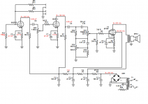
Hi, thank you all so much for help!
I added 1 Meg (well, 940 K to be honest, I use what I have on hands) from input triode grid to ground. I used 3 K for 6N2P B and 1.5 K for 6N2P A, so cathode voltages Now read 1,65 V and 2,1 V (Do I have to get them exactly the same?). Changed R3 to 1 K, so preamp plate voltages are now 190 and 170 V. I tried using 150 ohm resistor, but that did not change anything much.
I was using Gibsonette GA 8 schematic as one of guidlines and there preamp plate voltages are around 160 V, so I assumed thats normal for 12AX7.
C7 and C9 are changed to 2.2 uF. Heater voltage corrected to 6.3 V.
I added simple tone controls and 470 K resistor (not on schematic) between C6 and R5.
Nothing helped.
But I misunderstood Printer2 comment and changed volume potentiometer to 10 K, and strangely enough, that helped. Distortion comes in only when pot is halfway up and it is less there.The sound is lacking bass (I did change coupling caps), but at least its not distorting, I guess that is "blocking distortion"? it doesn't come in gradually, but cuts in sharply when gets to certain volume.
Anyway thats not real solution, probably there is some dumb mistake somewhere.
I will get resistors and caps with more precise values maybe that will help. And I have digital multimeter.
Attachments
Good!I added 1 Meg (well, 940 K to be honest, I use what I have on hands) from input triode grid to ground.
Do you mean the other way around, right? 2.1V for 6N2PB, 1.65V for 6N2PA? If so, yes, this is fine.I used 3 K for 6N2P B and 1.5 K for 6N2P A, so cathode voltages Now read 1,65 V and 2,1 V
No. But if both cathode resistors and both anode resistors are the same, then the two cathode voltages should be nearly the same. In your post #10, you said you had the same 740 ohm cathode resistors for both triodes, but you measured different cathode voltages of 1.9 and 3.2 volts. This showed me that something was wrong with your circuit.Do I have to get them exactly the same?
What was wrong was the missing 1 Meg resistor from 6N2PB grid to ground, which you have now fixed.
Good, that will work.preamp plate voltages are now 190 and 170 V.
In North America, when we say "B+", we mean the supply voltage, not the plate voltage (plate voltage is much less than supply voltage in the type of circuit in your preamp.) So when you said "B+3 = 130 Vdc, B+4= 150 Vdc" in your post #1, you caused some confusion for other people. No problem, though, we all figured it out now, and you've fixed the problems, so your circuit is now (almost) ready to work.Gibsonette...preamp plate voltages are around 160 V...
Good!C7 and C9 are changed to 2.2 uF. Heater voltage corrected to 6.3 V.
This type of tone control (Fender Brownface Bandmaster, etc) doesn't cause much signal loss, so by itself, it won't solve your distortion problem.I added simple tone controls
I see that you increased R6 to 300 k (it was 100k before). At the same time, you reduced the 1Meg I suggested to 470k. The combined effect of these two changes was bad. Instead of the circuit cutting down the signal 10 times, now it only cuts it down 2.5 times. Not enough.and 470 K resistor (not on schematic) between C6 and R5.
Nothing helped.
This is not strange - 10k is much too small, it destroys all the voltage gain from 6N2PB (now that triode does nothing), and as an accidental side-effect, it also destroys the bass response of your amplifier....changed volume potentiometer to 10 K, and strangely enough, that helped.
I'm attaching a way for you to use the 10k volume pot, and solve your gain problem, without losing all the bass and keeping 6N2PB from working. See the changes in pink in the attached image. You can use any resistor between 100k and 470k, adjust to suit your preference - the bigger the resistor, the more you can turn up your volume control without distortion.
Don't forget: you also have a volume control on your guitar. Turn it down if you want less distortion!
I think you will be happier if you change your whole amp a little - put a Fender Blackface tone control in between 6N2PB and 6N2PA. That will give you the clean tones you want.
-Gnobuddy
Attachments
Your output transformers . . . are they air-gapped laminations, made for a single ended output tube?
Or, were they made for a pair of push pull output tubes?
A push pull transformer would not be good for a single ended stage like you have.
Or, were they made for a pair of push pull output tubes?
A push pull transformer would not be good for a single ended stage like you have.
In post #1, the OP mentioned that one of his two output transformers came from the same TV (as his 6P14P output valve), and the other came from an old radio....output transformers...made for a single ended output tube?
Most likely, the TV and radio used single-ended power amplification circuits, so most likely, both OTs were designed for single-ended operation.
-Gnobuddy
I should probably clarify this comment a little....change your amp a little - put a Fender Blackface tone control in between 6N2PB and 6N2PA...
Each triode in your circuit will amplify the guitar signal by about 50 times.
The guitar itself typically puts out some 20 mV - 50 mV peak to peak when one string is picked lightly. But if you strum chords forcefully, you might get 1 volt peak to peak or more.
This means the first triode in the amplifier will typically have an output voltage somewhere between 1 volt peak to peak, and 50 volts peak to peak (that's 50 times 20mV, up to 50 times 1 volt).
With 300 volts B+, the triode is able to handle this much signal without clipping. So you don't get much distortion from the first triode.
Now, if you connect the first triode's output directly to the input of the second triode, as you (stroszek) have done, the second triode will start to overload with as little as 80 mV of signal from the guitar. This means you will get heavy distortion (from the second triode) if you turn up the guitar, turn up the gain control, and strum chords on the guitar.
So, in a guitar preamplifier, this recipe (gain stage -> volume pot -> gain stage) is used when you want to be able to overdrive the second triode, creating intentional distortion. The Fender Blues Junior uses a topology like this, enabling it to be used to play blues and rock music.
But if you don't want any distortion, you should follow a different recipe, the one Leo Fender used in his Blackface valve guitar amplifiers. That recipe is to have one gain stage, followed by a (very) lossy tone control, and then the second preamp stage.
This topology throws away most of the gain of the first stage before the signal reaches the second stage, so that there is not enough signal to overdrive the second triode. As we saw previously, the first triode doesn't get overdriven either. That means you get only clean guitar tone, no overdrive.
This recipe - clean tones only - is what Leo Fender wanted back in the 1950s and early 1960s, when rock music hadn't arrived yet, and blues music was still something mostly confined to black artists and audiences, and that too, far from Southern California, where Leo was based. You will find this recipe (gain stage -> tone control -> gain stage) in Fender's Blackface amplifier designs, such as the '65 Princeton Reverb.
In short, if you want nothing but clean tones, you need to lose a lot of signal between the two triodes. The quickest way is to insert an additional resistor as I showed you in post #17. But a better way is to put a lossy tone control circuit in between the two triodes, just like Leo Fender (or his technician) did in the 1960s.
The attached image shows part of the AA1164 Princeton Reverb schematic. Leo not only put the lossy tone control between the two triode gain stages, he also added a volume control there, which can throw away even more of the signal after the tone control has already thrown away most of it. That second triode is never going to overload.
-Gnobuddy
Attachments
- Home
- Live Sound
- Instruments and Amps
- Help with se tube amp or kill me!