Recently I was able to get the schematic of my amp, a Pioneer A757. While I do have some basic understandig of amplifiers, I am by far not an expert, so if somebody could give me a few hints on how this schematics works, I would highly appreciate it.
I am also interested in mods/tweaks to improve the sound, if you see any oportunity in this respect. I like the sound of the amp, but it is a bit on the "dry" side for me - I'd have some more warmth, even at the cost of more distortion.
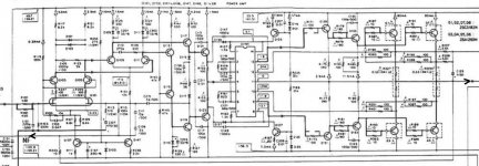
I find the schematics itself also pretty interesting, thoroughly in the style of late 80's - lots of components. I understand that the PA0016 IC is responsible with the biasing of the power stage, but I have really no clue what it really does - couldn't find a datasheet.
I also don't see a global feedback loop: there is one starting BEFORE the final stage to the diff amp, but I might oversee something there.
Later edit: there is global NF, I just missed it. The point where R243, C109, R115 get together is connected to the output of the amplifier.
I am also interested in mods/tweaks to improve the sound, if you see any oportunity in this respect. I like the sound of the amp, but it is a bit on the "dry" side for me - I'd have some more warmth, even at the cost of more distortion.
I find the schematics itself also pretty interesting, thoroughly in the style of late 80's - lots of components. I understand that the PA0016 IC is responsible with the biasing of the power stage, but I have really no clue what it really does - couldn't find a datasheet.
I also don't see a global feedback loop: there is one starting BEFORE the final stage to the diff amp, but I might oversee something there.
Later edit: there is global NF, I just missed it. The point where R243, C109, R115 get together is connected to the output of the amplifier.
Attachments
Cant understand why no one replied ! Do you have the schematic for the 757 ? post it here or something so we can take a look.
What mods have you done upto now ?
I am in the process of tuning the A-400 amp, sounds pretty good upto now with just the addition of some blackgates. Biasing and more blackgates in the feedback loop next.
dennis
What mods have you done upto now ?
I am in the process of tuning the A-400 amp, sounds pretty good upto now with just the addition of some blackgates. Biasing and more blackgates in the feedback loop next.
dennis
one way to add some "warmth" is to increase the output impedance (reduce damping factor) in a controllable way. the simplest way to do this is to add a small amount (about 0.1-0.5 ohm) of resistance between the amp and the speakers. this comes at the cost of a small bit of power, and the larger the resistance the higher the wattage required for the resistor. a 5w resistor should be ok for 0.1 ohm, and a 10w resistor for 0.5 ohm. the metal cased ones that can be mounted on a heat sink are best, and the Dale ones are noninductive. 1ohm would be too much, since that would give a damping factor of 8, although you might like the sound if you say that the amp as it is is too "dry". just remember that whatever resistance you use has to dissipate it's share of the wattage. damping factor is ZL/Zo (load impedance divided by output impedance) and is a measure of how much the amp damps the effects of back EMF from the speaker (a speaker is very similar to a linear DC motor).
Hi bzfcocon,
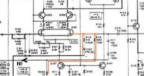
It's hard to read the incomplete low res picture.
The feedback loop is however visible, see attached picture.
I also don't see a global feedback loop
It's hard to read the incomplete low res picture.
The feedback loop is however visible, see attached picture.
Attachments
I have an A757 with a problem too... And I was happy with the piece of the schematic. But some info is hard to read.
The first problem with the amp was 4 blown OPT's... I removed them...
Next problem was that one of the +/-24V psu's was dead. There was one 5 Ohm resistors open on the psu board right under the transformers. After replacement one output channel was OK.
I bought 8 (for sure) new Toshiba OPT's, the originals. After replacment there was sound with distortion... But one step closer! After some inspection AND replacing the PA0016 IC from the working channel to the bad channel the sound was better but the QCurrent was not good...(but the other PA IC is bad, that's clear)
Later I found a blown 2SC1845 just before the PA0016... But that's not the only problem...
I thinkt it's the best to buy a servicemanual for more info... I could buy new PA0016's for € 15,00 and bought 2 of them... (when the amp is working I replace both of them)
But first I have to find out the problem with the Qcurrent... It's nog the PA0016. There is an unballance in the voltage over the PA0016 on pins 1,14 and 7,8. Normal it's around 2 x 3V and now it's 9V en -2.5V
More comes next...
Pioneer A-757
Hi,
If you're after just the bare schematics, that's what I can help you with.
I have a reasonably good scan, at least far better than what was uploaded here.
Send me your e-mail address for a copy.
Kind regards,
/tri-comp
Hi,
If you're after just the bare schematics, that's what I can help you with.
I have a reasonably good scan, at least far better than what was uploaded here.
Send me your e-mail address for a copy.
Kind regards,
/tri-comp
Hello Tricomp,
You can help me very much if you send me your scan of the schematic...
A problem is that I can't send you a mail because I'm a new user and in moderation... I will put my emailadres here and hope that it works that way... A mailadres what you can use is richardswebdisc@gmail.com . . . I hope it will work
Kind regards,
Richard
Hello Tricomp,
Many Thanks for the schematic... 🙂 I printed it on A3 paper, it's very good!
I send you a personal too...
Many Thanks for the schematic... 🙂 I printed it on A3 paper, it's very good!
I send you a personal too...
to tricomp
hi,
i also have a pioneer a757 to repair,
many resistors are blowing up,so i need
the schematics,can you the schematics
send it to me?
many thanks, char
hi,
i also have a pioneer a757 to repair,
many resistors are blowing up,so i need
the schematics,can you the schematics
send it to me?
many thanks, char
Hallo Char,
Do you have other questions about this amp... You can mail me in dutch!
My 757 is working great. It was one of the hardest repairs I ever did but I have no regrets! If you need a new PA0016 chip you can order it in Almere (Pioneer Holland), I did it too, it was € 15,00 each... Not very expensive for a custom build chip. And check the 10 and 100 Ohm resistors too!!!
re 757
hallo,
ja, de pa0016 is stuk, gek genoeg zijn eindtorren goed,
maar diverse weerstanden zijn verbrand,vandaar vraag om
schema.
gr char
hallo,
ja, de pa0016 is stuk, gek genoeg zijn eindtorren goed,
maar diverse weerstanden zijn verbrand,vandaar vraag om
schema.
gr char
help
Hi rjedb!
I'm also in trouble with the Pioneer IC PA-0016 of my Receiver Pioneer 9700S.
As I'm new here I could't remit a MP to you.
So may I ask you to pls remit a copy of the schematics and the site address of Pioneer Holland where I may find the IC for replacement (Tried via google but failed).
Thanks for your help.
Regards, Paulo.
Hello
Please Help Me.
I find the Pioneer PA0016 IC schematic diagramm,because this crash again and again in the Pioneer A-X550 AMP.And my mechanic talk how not understand this problem.
Thanks
Please Help Me.
I find the Pioneer PA0016 IC schematic diagramm,because this crash again and again in the Pioneer A-X550 AMP.And my mechanic talk how not understand this problem.
Thanks
Greeting
i have the same problem with pioneer A441,
can you please send me the schematic.
Best regards
thank you in advance .
i have the same problem with pioneer A441,
can you please send me the schematic.
Best regards
thank you in advance .
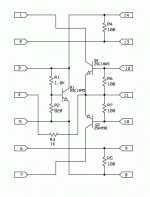
Here is the schematic of the infamous PA0016, (a few are still kicking around at various sites at astronomical pices, 20-30 USD a piece) this might help to replace it with discrete components.
One can actually build it on a tiny pcb with SMD parts, and fit it to the place of the original IC
One can actually build it on a tiny pcb with SMD parts, and fit it to the place of the original IC
Attachments
Greetiing
i have the IC PA0016 i have 10 of it... i needed the schematic for the AMP A441 i have a pdf schematic drawing can hardly see the numbers and letters and the voltages over the pins ...
if possible and you have the schematic, i l be much appreciated and grateful for that.
thank you for your fast reply.
Best regards
I have a M90a where one chanel has 0 bias and 70V DC on the output. Previous owner says it blew when his preamp blew...
I have so far checked all diodes and almost all transistors...all seem good.
If you want to sell a PA0016 I'm interested...I am starting to suspect that IC.
I have so far checked all diodes and almost all transistors...all seem good.
If you want to sell a PA0016 I'm interested...I am starting to suspect that IC.
I want to know a bias servo circuit to upgrate usual AB power amps. Should I prefer this discrete version of PA0016 from post #15?
Check also post #22 under
Dynamic Bias - Active Bias - Automatic/Self biased - Overview wanted
Check also post #22 under
Dynamic Bias - Active Bias - Automatic/Self biased - Overview wanted
Last edited:
any news?I want to know a bias servo circuit to upgrate usual AB power amps. Should I prefer this discrete version of PA0016 from post #15?
Check also post #22 under
Dynamic Bias - Active Bias - Automatic/Self biased - Overview wanted
under
https://www.diyaudio.com/forums/solid-state/202684-class-siblings-17.html#post2864279
and
Bob Cordell's Power amplifier book (post 2329)
and
Class i and siblings
are some informations.
https://www.diyaudio.com/forums/solid-state/202684-class-siblings-17.html#post2864279
and
Bob Cordell's Power amplifier book (post 2329)
and
Class i and siblings
are some informations.
- Home
- Amplifiers
- Solid State
- Help with schematic