Ohh...maybe that's why nobody answers my calls 😀....turned out that the 2-pin plug of the charger autonomously decided to crawl out of the socket, vertically.
Actually, I just replugged the monitor PSU and the phone charger myself so it is some consolation to know that
even with different mains plug/socket designs, globalisation leads to very consistent global product failures too.
Skippy? A bit too "gamey" for me but bon apetit - plenty of seconds where she came from.

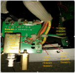
Looks like it probably can, but please should a picture of the actual transformer. An ohmmeter can be used to identify the various taps on the primary.
Note that you are likely to require another fuse and possibly another type of spark killer cap as well.
Note that you are likely to require another fuse and possibly another type of spark killer cap as well.
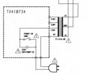
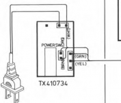
Thank you for answering me i'll send photos later , at the outpout of the primary transformer there is marked 0 volt on green and yellow wire , orange and brown there is 2*115 volts and on a white it's marked TP
"TP" probably reads TF = thermal fuse. I am guessing right now it's going mains --> TF --> 0 V -(primary)-> 115 V --> mains or something like that, right? (The second 115V winding should be either unused or wired up in parallel to the first.)
You will have to wire up both 115 V primaries in series with correct phase. So you should disconnect the wire from the 115 V that's in use now and rewire things accordingly. There is no standard for this, so the first 115 V will have to be connected to either the second's 0 V or 115 V with an extra wire (I'd try what's right next to it first).
Nothing bad should happen if you get phase wrong, you just won't have much output voltage to speak of (because you just wired up the transformer as a big common-mode choke and the magnetic fields of the two windings cancel out) and things obviously won't work.
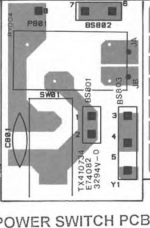
Make sure you put in an appropriate mains fuse. Take out the existing part and read out its value, maybe with a loupe. You'll need one with half the amperage and twice the voltage rating, same kind of acting characteristic. You might find something like a T 4 A 125 V, which you'd replace with a T 2 A 250 V.
You will have to wire up both 115 V primaries in series with correct phase. So you should disconnect the wire from the 115 V that's in use now and rewire things accordingly. There is no standard for this, so the first 115 V will have to be connected to either the second's 0 V or 115 V with an extra wire (I'd try what's right next to it first).
Nothing bad should happen if you get phase wrong, you just won't have much output voltage to speak of (because you just wired up the transformer as a big common-mode choke and the magnetic fields of the two windings cancel out) and things obviously won't work.
Make sure you put in an appropriate mains fuse. Take out the existing part and read out its value, maybe with a loupe. You'll need one with half the amperage and twice the voltage rating, same kind of acting characteristic. You might find something like a T 4 A 125 V, which you'd replace with a T 2 A 250 V.
- Status
- Not open for further replies.
- Home
- Amplifiers
- Solid State
- Help with Rotel voltage reconfiguration