it could be red red orange silver
22k 10%
can you find a similar one in the circuit and measure it.
red = 2
org = 3 or x 1000
silver = 10%
so 22000
22k 10%
can you find a similar one in the circuit and measure it.
red = 2
org = 3 or x 1000
silver = 10%
so 22000
Last edited:
hi thanks for the reply i found another and that is blown too i think i have found a schematic but not too sure how to use it the resistor location says c531 and the other one also reading open says c710
TECHNICS SU X501 SCH Service Manual free download, schematics, eeprom, repair info for electronics
TECHNICS SU X501 SCH Service Manual free download, schematics, eeprom, repair info for electronics
hello.
have you tried to measure it with a multimeter?
was the res "overheated"?
could be red violet orange............27k ?
greets
have you tried to measure it with a multimeter?
was the res "overheated"?
could be red violet orange............27k ?
greets
hello.
have you tried to measure it with a multimeter?
was the res "overheated"?
could be red violet orange............27k ?
greets
yes multimeter is reading open circuit
If they are called C531 and C710, then they are likely small ceramic capacitors instead of resistors. Try measuring them as caps. Red-red-orange would be 22000pf, or 0.022uf. They will measure open on a resistance reading. COnsidering what they are, I wouldn't be surprised if they were really OK.
Your schematic shows both those call numbers as 0.022uf caps. In this case both are coupling two different sections of grounds within the amp.
Your schematic shows both those call numbers as 0.022uf caps. In this case both are coupling two different sections of grounds within the amp.
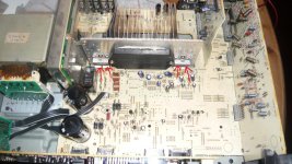
Ah right capacitor ! (confusing this electronics ) well im learning,, would you mind having a look at the photo of the amp i have no sound output ,, i have tested the transistors marked with red arrows , also i have a audio signal generator but not too sure where to inject the signal to ,,would appreciate any help
mark..
mark..

hi looking at schematic on the main chip on heatsink all voltages seem right except for pin 8 which should be -.1 i have -42 and pin 9 should be -42 i have -4.2
Above post should have said voltages on pin s on the main SVI 3204 amp chip i have removed it and have a short between pins 2 and 11 i have traced the tracks back from these pins and checked the resistors which seem ok is there anywhere else i should pay particular attention to?
I have got a new chip ordered off "taobao" !! (chinese ebay) there you seem to be able to find anything you cant anywhere else ,,
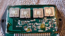
here is photo of chip the short seems to lead back to this component not sure what it is though .
I have got a new chip ordered off "taobao" !! (chinese ebay) there you seem to be able to find anything you cant anywhere else ,,
here is photo of chip the short seems to lead back to this component not sure what it is though .

very interesting assembly.
I think all the black numbered components are resistors.
I also think the brown bodied without ident are capacitors.
No smd transistors in sight. All in the two chips.
Is this an example of wafer level assembly integrated into smd?
Could someone with knowledge talk us/me through what we are seeing?
I think all the black numbered components are resistors.
I also think the brown bodied without ident are capacitors.
No smd transistors in sight. All in the two chips.
Is this an example of wafer level assembly integrated into smd?
Could someone with knowledge talk us/me through what we are seeing?
Looks like a little cap to me. I have never cracked open one of those amplifier ICs before.
i hadnt intended to open it it seemed to come apart when i prised it off the heatsink
Is there anything i should be checking on the rest of the amps circuits i dont want to solder in the new one and blow that too ?
cheers
mark
- Status
- Not open for further replies.
- Home
- Design & Build
- Parts
- help with resistor
