I'm trying to build a preamp for guitar in a pedal format. I'm worried about the output impedance of the circuit, so I'm trying to blend it with another schematic, which uses a cathode follower buffering circuit for the output. I have two 12ax7s.
Here's the #1 preamp:
http://img35.imageshack.us/img35/8529/pre1.jpg
This is #2 preamp:
http://img204.imageshack.us/img204/4031/hotboxsch.gif
This is my solution to blend the two circuits together:
http://img25.imageshack.us/img25/4927/sch.gif
Do you think this would be correct? If not, any help or suggestion is really appreciated. Thanks.
You shouldn"t have to worry about the output impedance if you are plugging the output of the Preamp/Pedal into a guitar amp , a Guitar amp has a very high impedance input so it can handle a highish impedance input .......
If you want a very low impedance output from your pedal try putting an opamp or Transistor buffer after the tubes , you can power the opamp or transistor of the fillament voltage .....
Haw are you gonna fit 2 or 3 tubes plus a HV Tube PSU into a pedal enclosure ??
Cheers
If you want a very low impedance output from your pedal try putting an opamp or Transistor buffer after the tubes , you can power the opamp or transistor of the fillament voltage .....
Haw are you gonna fit 2 or 3 tubes plus a HV Tube PSU into a pedal enclosure ??
Cheers
You shouldn"t have to worry about the output impedance if you are plugging the output of the Preamp/Pedal into a guitar amp , a Guitar amp has a very high impedance input so it can handle a highish impedance input .......
If you want a very low impedance output from your pedal try putting an opamp or Transistor buffer after the tubes , you can power the opamp or transistor of the fillament voltage .....
Thanks for your answer.
Well, I have two 12ax7s, if I don't use the buffer I have one spare triode anyway. It's an all tube design, I'd rather use tubes instead of transistors or opamps. Any more opinions on the circuit are welcome.
Haw are you gonna fit 2 or 3 tubes plus a HV Tube PSU into a pedal enclosure ??
Simple: making a big enclosure 🙂
If you are interested in a very small easy to make PSU for yer tubes that doesn"t require big high voltage transformers (just a 12v ac one) then you might be interested in this one ....
http://www.ledsales.com.au/kits/nixie_supply.pdf
http://www.ledsales.com.au/kits/nixie_supply.pdf
hello.
is the power supply voltage equal for the two different schematics?
what is the reason for that switch at the output of your solution?
is the power supply voltage equal for the two different schematics?
what is the reason for that switch at the output of your solution?
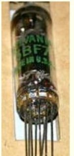
it might also save some space if you use subminiature tubes. they are mostly military surplus, but available, usually cheaper than 12AX7's. i've used 6BF7 dual triodes to make some good sounding preamps. they are about the height of a 12AX7 (maybe a little shorter). but 1/2 the diameter. they're also called "pencil" tubes because of their small diameter. the filaments can be run from 12V with 2 tubes each sharing 6V, and plate voltages of 24 to 100V work well. they work well in any normal preamp, about the same gain as a 12AT7 (a bit less than a 12AX7, but with a properly designed preamp, it's more than adequate). with the low to medium plate voltages, they also work well with semiconductors. you could get a LOT of gain using a MOSFET current source as a plate load. the subminis also run cooler (relatively) than 12AX7s do. the filament current is lower, and the tube uses less plate current.
BTW, i just noticed after finishing the message that the thumbnail picture shown below is just about the same size as the actual tube......
BTW, i just noticed after finishing the message that the thumbnail picture shown below is just about the same size as the actual tube......
Attachments
mjf said:hello.
is the power supply voltage equal for the two different schematics?
what is the reason for that switch at the output of your solution?
The power supply voltage is 300V in both cases.
The switch in my solution is to bypass the preamp when not in use, like an effect pedal. Sorry, I erased the first part of the switch from the previous schematic but I'm sure you get the idea.
What I'd like to know is if my solution blends the two circuits correctly or if I've made any mistakes, specially the components after the volume pot.
Thank you.
hello.
i think it should work.
you can add a rc filter into the power supply lines (res with a few kiloohm and an elco with a few uf /350volt or better) for lower noise...
the 100k res behind the volume pot is a liittle bit high........perhaps you can reduce it to 68 kohm .
if you do not need two inputs build only one.
for safety you can use 400v voltage rating or better for the filmcaps.......
that muting - bypass switch is an own discussion......
take care of the power rating of the resistors you use.........
greetings................
mjf said:
the 100k res behind the volume pot is a liittle bit high........perhaps you can reduce it to 68 kohm .
Thanks mjf I'll do what you suggest, that's a great help.
Let me ask you what's the effect of that 100K resistor after the volume pot, and why do you suggest changing it to a 68K? Can it be eliminated completely?
I'm a newbie and I'm trying to learn. Thanks again.
hello.
mostly there is a 1 kohm res at the grid - a gridstopper res ,which should help to prevent oscillationes,it should be built in near by the grid (e.g. at the socket).i would not eliminate it.
i presume the reason for that high value is some kind of sound tuning - perhaps it makes the sound a little bit more "sweet"......
so i thought about 68kohm........as used in the other stages.
but you can try it as you think.........
greetings.........
- Status
- Not open for further replies.
- Home
- Live Sound
- Instruments and Amps
- Help with preamp