After a few days of learning Vituixcad, I've come up with a crossover simulation for a 6.5" and 1" 2 way.
This is based on published datasheets only- not measuring my own drivers. That's a different project for a different year.
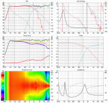
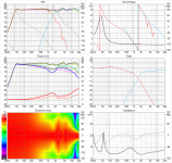
The goal was to practice crossover design, so I used a 20L cabinet with port tuning to 42Hz. The downside is that the tweeter hole is pre-cut for 110mm x 6mm deep tweeter. eg. Fountek CD3.0 or Seas T25CF002, and the specific location of the tweeter on the baffle causes a wicked 4KHz peak due to diffraction.
Attached are two crossover designs.
Any glaring problems?
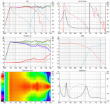
One has better phase alignment at the crossover point.
The other has better directivity/spinorama ie. CEA 2034-A.
But I can't get both. At least not yes. Is this my rubbish crossover design, or is it just inherent in 2 ways without waveguides?
How much weight should I place on a spinorama type simulations, when it's only a simulation based on SPL traced datasheets?
Before building the crossover, are they any obvious faults that one can see from the VituixCad 6 pack?
Brutal honesty appreciated. 😛
This is based on published datasheets only- not measuring my own drivers. That's a different project for a different year.
The goal was to practice crossover design, so I used a 20L cabinet with port tuning to 42Hz. The downside is that the tweeter hole is pre-cut for 110mm x 6mm deep tweeter. eg. Fountek CD3.0 or Seas T25CF002, and the specific location of the tweeter on the baffle causes a wicked 4KHz peak due to diffraction.
Attached are two crossover designs.
Any glaring problems?
One has better phase alignment at the crossover point.
The other has better directivity/spinorama ie. CEA 2034-A.
But I can't get both. At least not yes. Is this my rubbish crossover design, or is it just inherent in 2 ways without waveguides?
How much weight should I place on a spinorama type simulations, when it's only a simulation based on SPL traced datasheets?
Before building the crossover, are they any obvious faults that one can see from the VituixCad 6 pack?
Brutal honesty appreciated. 😛
Attachments

Last edited:
One is closer, but you have sought to control the slopes in both cases which is important.One has better phase alignment at the crossover point.
The spinorama is rather non-specific.The other has better directivity/spinorama
Look at 4k. If VituixCad is configured properly with your data, it gets wide at 4k, and this comes after 1k5 which is narrow. This variation has the potential to leave the treble a little disjointed.
Hi Allen,
Thanks for your response. I'll be sure to re-read through your Designing Crossovers without measurements sticky.
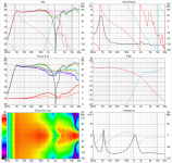
After your comments and some thinking, I went back and tried to optimise for both phase alignment at the crossover point, and sound power. This speaker is designed for listening without a subwoofer, at 2-3M distance in a normally reflective room.
My VituixCad crossover programming is based on off axis responses from the baffle Diffraction tool.
Nice indoor project whilst in Australian hotel quarantine. 😛
regards.
Thanks for your response. I'll be sure to re-read through your Designing Crossovers without measurements sticky.
After your comments and some thinking, I went back and tried to optimise for both phase alignment at the crossover point, and sound power. This speaker is designed for listening without a subwoofer, at 2-3M distance in a normally reflective room.
My VituixCad crossover programming is based on off axis responses from the baffle Diffraction tool.
Nice indoor project whilst in Australian hotel quarantine. 😛
regards.
Attachments
Last edited:
Designing for precise phase alignment is off-point. Some designs even call for a specific separation. At the least be aware that the tolerance is much higher on the in-phase side than the out of phase side so chasing the notch is just going to keep you up at night.
Reducing the narrowing at 1k5 is more likely to be asking for a lower crossover point.
Reducing the narrowing at 1k5 is more likely to be asking for a lower crossover point.
What do you mean by "off point?" I've interpreted that has having limitations, that the perfect on-axis phase alignment gets screwed up once the listener (or mic) is moved around from the design axis?
Even to verify my design, I'm going to have to measure outdoors at 1m, or indoors at 0.5-0.6m(likely), so my perfect looking reverse null will probably fade away...
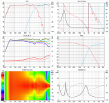
Crossover version 4.
Might be time to order the passive components, suck it and see...
Even to verify my design, I'm going to have to measure outdoors at 1m, or indoors at 0.5-0.6m(likely), so my perfect looking reverse null will probably fade away...
Crossover version 4.
Might be time to order the passive components, suck it and see...
Attachments
Last edited:
Last edited:
How much weight should I place on a spinorama type simulations, when it's only a simulation based on SPL traced datasheets?
That would depend a lot on how they were measured. The Baffle diffraction simulator in Vituix is pretty good though so it shouldn't be way off. If the physical alignment or acoustic time alignment was different to your model then the response might not work the same as the prediction. This is the reason why the help file stresses the need to measure the time relationship of the drivers properly.
I would say the first one you posted looked the best on paper, hard to say if that would work out as well in practice. All the other later versions introduce peaks in the off axis response which is not usually desirable.
This one has fairly flat on axis and listening window predictions and the power and off axis response are the smoothest of the different options.
- Home
- Loudspeakers
- Multi-Way
- Help with passive crossover design- VituixCad