I am having a bit of trouble with a kit amplifier in what I believe being the output stage matching. Had issues before where one bjt would get hotter a lot fast than the others (current hogging) till it blew. Then after matching all outputs to within 2-4% of hfe and vbe, The amplifier ran fine, I was good till I did something and blew the amp...
The OP stage is 4 pairs of njw0302/0281 connected via 0.25ohm ER's and 4.7ohm base resistors from the drivers.
I replaced the shorted device, and after playing for a few minutes into a lowish load (4 ohms in bridged mode with +/-58vdc rails) one device blew again. I know the 4 pairs can take this load as the amp had been working fine for several weeks running stable.
As soon as it blew, I felt the temps on all of the devices by touch and the one that blew was a lot hotter than the rest, I assume it is was hogging current.
The other 3 have hfe ranging from 115 to 117 and the blown one was 107. The Vbe showed similar spreads. The replacement was not an optimal match as I did not have more devices to match it better, so stuck in the closest one I had.
The question I have is... given the devices I have , Is there a solution where I trim the current to each device? eg. should I increase base resistors from 4.7 to 20 or 30 ohms to allow better current sharing? or ER's? It seems these super beta devices like to take up all the load onto themselves.
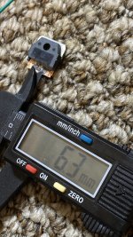
I thought about the devices being fake, but they seem ok from what I can tell (see pic) , the wafer is over 6mm which is similar to the other 100-150w bjt's I have seen.
The key I feel is the fact that only one device got hot, not the others. After removing that device, the other 3 on the rail seem to work fine... all share the same temp.
What do the experts suggest?
The OP stage is 4 pairs of njw0302/0281 connected via 0.25ohm ER's and 4.7ohm base resistors from the drivers.
I replaced the shorted device, and after playing for a few minutes into a lowish load (4 ohms in bridged mode with +/-58vdc rails) one device blew again. I know the 4 pairs can take this load as the amp had been working fine for several weeks running stable.
As soon as it blew, I felt the temps on all of the devices by touch and the one that blew was a lot hotter than the rest, I assume it is was hogging current.
The other 3 have hfe ranging from 115 to 117 and the blown one was 107. The Vbe showed similar spreads. The replacement was not an optimal match as I did not have more devices to match it better, so stuck in the closest one I had.
The question I have is... given the devices I have , Is there a solution where I trim the current to each device? eg. should I increase base resistors from 4.7 to 20 or 30 ohms to allow better current sharing? or ER's? It seems these super beta devices like to take up all the load onto themselves.
I thought about the devices being fake, but they seem ok from what I can tell (see pic) , the wafer is over 6mm which is similar to the other 100-150w bjt's I have seen.
The key I feel is the fact that only one device got hot, not the others. After removing that device, the other 3 on the rail seem to work fine... all share the same temp.
What do the experts suggest?
Attachments

Last edited:
Since the one with the lowest hfe blew not sure it was current hogging. And the matching of the transistor hfe that you had was very close. Most comercial amps are not even matched. Are you sure the transistor and bias spreader were properly heat sinked? You can measure the current to see if hogging is happening, by measuring the voltage across the .25 ER.
Last edited:
I used silpads, so that may not be the issue. Also I measured the hfe with a TC-1 which only uses something like 6ma? to drive the DUT, In real life there is a lot more current flowing... which may have caused it to current hog.
Something is not as advertised. Perhaps one resistor is not the same as the other 3? Perhaps the speaker/load is connected to the wrong end of that resistor? Perhaps the one resistor is shorted?
Yes, something like that.
The values you measured are way more matched than average, and amps are not exploding all over the place.
Still suspect marginal fakes where the weaker one dies first and protects the others by blowing the main fuse but also would not discard a gross misconnection error.
I was burnt by a lot of fake TDA2050 which overheat and explode, even no load, no signal, so it´s clearly a voltage rating problem, with TDA2050 sized rails: +/-22V ,yet are happy as a puppy and run cold all day long at +/-14V , so they are probably relabelled TDA2030 or similar.
Not junking them, just will use them within demonstrated parameters.
I stopped a run of 25/30W 10" speaker guitar amps and am starting another rated 15W with 8" speakers.
Nothing goes to waste, that´s for sure.
The point being I suspect you got burnt with a lot of "almost usable" transistors.
Personally I´d test them, at real world voltage and current, but no sure you will set up a measurement jig for a single use situation.
Last edited:
Something is not as advertised. Perhaps one resistor is not the same as the other 3? Perhaps the speaker/load is connected to the wrong end of that resistor? Perhaps the one resistor is shorted?
I know... Checked the resistors.
I have considered the fake devices theory too and it could be the case indeed ... I just wonder why one of them get hot and the others don’t.
Yes, something like that.
The values you measured are way more matched than average, and amps are not exploding all over the place.
Still suspect marginal fakes where the weaker one dies first and protects the others by blowing the main fuse but also would not discard a gross misconnection error.
I was burnt by a lot of fake TDA2050 which overheat and explode, even no load, no signal, so it´s clearly a voltage rating problem, with TDA2050 sized rails: +/-22V ,yet are happy as a puppy and run cold all day long at +/-14V , so they are probably relabelled TDA2030 or similar.
Not junking them, just will use them within demonstrated parameters.
I stopped a run of 25/30W 10" speaker guitar amps and am starting another rated 15W with 8" speakers.
Nothing goes to waste, that´s for sure.
The point being I suspect you got burnt with a lot of "almost usable" transistors.
Personally I´d test them, at real world voltage and current, but no sure you will set up a measurement jig for a single use situation.
If they are fakes... the biggest issue is consistency then... in some kits they run fine on 91vdc rails, in others they fail after 10 minutes (both instance they were operated within the OP stage SOAR (but probably beyond the SOAR of a single device if it wanted to hog current)...
This is why I asked about the feasibility of trimming base resistors... does that work reliably?
If the part can´t stand the voltage,no biasing or trimming will help it.
I *could* use my fake TDA2050 by heavily derating them.
91V rails are murderous, maybe you can use these transistors (if you have many) in a smaller amp, say with 50/55 V rails.
Although the real storage bin for them is the corner junk bin.
I also got burnt by some 4700 x 63 caps, I measured and they become very lossy between 61 and 68V .
Being a cheap rat I did not junk them but will use them in 50V rails amps.
Mind you, most of them can be used with 60V rails, but it´s a bad practice workin so close to*real*voltage capability, you always neaed at least 20% margin ... and even more in semiconductors.
PS: no need to quote my posts in full since they are just above , just quote 1 line to know what are you answering to.
There is an anti-clutter warning in the Forum, but nobody cares.
You could have quoted just:
Originally Posted by JMFahey View Post
Still suspect marginal fakes where the weaker one dies first and protects the others by blowing the main fuse but also would not discard a gross misconnection error.
Last edited:
I should have been clearer... I have tried the following scenarios:: let’s say this is kit #2.
Kit #1. Runs fine with 91v with same devices. Load is a single JBL 2035 8 ohm (7.2 dcr) driver. Still runs fine. The PSU on this is an Antek 1kva trafo and 8x 10kuF caps. Kit 1 runs single ended into the woofer.
Kit #2. Is a bridge of 2 channels of the same kit. Thus running at lower voltage. Ran fine at 60v for weeks bridged into 4 ohms. 800va 42-0-42vac unit.
Since kit 1 and 2 were identical, and kit 1 ran fine at 91vdc, I applied 91vdc to kit 2 with a 4 ohm load but hardly any voltage drive present. Maybe 0.5v across the speakers just as a quick test to hear something. It ran fine for a few minutes then died.
I then repaired it and went back to 60v and that’s where kit 2 blew again after 10 minutes with the replaced bjt running hotter than the others.
It ran fine at 60v bridged before. I realize it’s an apparent 2 ohm load which is torture.... but it ran fine before for weeks, and all 4 OP devices were roughly the same temp. It is obvious to me that one device runs hotter than the other is a theme with this kit... and I suspect its because the base resistors are rather low for a high beta OP device (4R7)
The purpose of this post was to confirm this line of investigation....
Last edited:
In the DIY world those devices are usually used as drivers for their higher powered big brother version NJW3281/1302. SOA isn't very good at 91V rail voltage.
I bought in some irfp240/9240 from China.
They worked great, well for 10 minutes when I unplugged my soldering iron !
The transistors were going into breakdown if they saw a spike on the power rails.
Probably due to poor specs and being fake.
SO I bought some from RS Components and the amp has been fine for about a year now.
Two possible answers:
1/ Buy from a reputable dealer.
2/ Put loads of decoupling on the rails and protect mains input with MOV's.
In 40 years of amp building I have never matched transistors in my amplifiers either self designed or designed by others.
The fact the faulty transistor is red hot suggests breakdown voltage was reached and they turned on fully.
Buying in transistors etc from ebay/China is a big lottery.
I have had some rubbish off ebay and China but also found bargain excellent analogue to digital converters. I have also had crap a2d converters too.
Thanks Nigel...
When I was a poor student... and I wanted higher rails I did not know Vce ratings then, I used to think Vce of 100 is good for +/-100v rails as I thought the trannie sits on one rail only... during those days I upped the rails on a kit using Mj15003/4 (140vce) to +/-90vdc. A few died along the way and each time I'd replace them with a Mj15024/5. I didnt know any better... BUT before I gifted that frankenstein to my cousin to moved out of the city , It still had 15003/4's working just fine. Those were some rugged OP devices...
When I was a poor student... and I wanted higher rails I did not know Vce ratings then, I used to think Vce of 100 is good for +/-100v rails as I thought the trannie sits on one rail only... during those days I upped the rails on a kit using Mj15003/4 (140vce) to +/-90vdc. A few died along the way and each time I'd replace them with a Mj15024/5. I didnt know any better... BUT before I gifted that frankenstein to my cousin to moved out of the city , It still had 15003/4's working just fine. Those were some rugged OP devices...
Base resistors are counter productive wrt load sharing, vs Emitter resistors help share the load.
And whenever a transistor fails, the resistors all need to be verified. Burnt resistors values change.
Whenever you have a failure, you need to run a curve trace on the used devices. An Ohm-meter test is not enough. You need to verify the breakdown voltage. Years ago when I did this for a living, I built a simple tracer box with a small tube amp power transformer, a 10W, ~10K resistor and a scope with X-Y inputs.
Create Your Own I-V Curve Tracer | Circuit Cellar
Note that you can do a simple breakdown voltage check with a high voltage supply, a resistor and a voltmeter.
Last edited:
Here is something interesting (for the gentleman that said base resistor trimming was not the way to go) All other base resistors show a bias voltage of 0.4mV across 4r7, the OP device that keeps blowing (this time I put a known genuine part) shows 0.6mV.
On the ER's all others show 4mV and the new one shows 6.5mV across 0.25ohms. This is running on reduced rails and I have not fully trimmed bias yet, but why is there extra vdrop on the device slot that keeps on blowing? its miniscule, but there has to be a correlation...
On the ER's all others show 4mV and the new one shows 6.5mV across 0.25ohms. This is running on reduced rails and I have not fully trimmed bias yet, but why is there extra vdrop on the device slot that keeps on blowing? its miniscule, but there has to be a correlation...
Last edited:
I don't have a schematic, but i can post some pics of an unfinished board (the one I have is messy with missing traces etc. :-D . But the trace is not an issue, I have checked continuity.
A good picture of the problem board is more useful. Someone may see what is actually wrong. It's quite easy to overlook a wrong part if you've been looking at the amp for days. Fresh eyes can spot something amiss instantly quite often.
Replacing the blown transistor with one genuine part is not the way to go.
They should all be replaced by genuine parts.
You are talking about two different resistors values on the outputs emitters.
They should all be the same value.
If not you have probably found your problem.
I had a Chinese IC arrive today so soldered it in a pcb where the previous 4 have worked fine.
This one worked very badly. So its a lottery with Chinese/Ebay components.
Last edited:
Nigel, I get what you are saying... but I am trying to make this work as I have 6 boards (12 channels) each channel has 8 OP devices... I am not in the mood to buy another 96 OP devices... This is going in Home theatre duties, so not ultra critical listening... just need them not to blow up and make lots of power.
Last edited:
- Home
- Amplifiers
- Solid State
- Help with output mismatching