Hi!
Lets take this from the begining...
At first i have to say i'm not write or speak English so well...
A friend gave me a sub woofer (Audio pro SUB+) that was stone dead when plugged to the mains.
I thaught it would be an easy one to fix, and started right on to trouble shoot the electronics.
This is a special amplifier design (ACE bass) and can only drive the specific driver it ment for.
* Transformer was no longer able to put out any voltage.
* both output transistors shorted.
I replaced the transformer with two toroid transformers with almoast the same spec, and new Output transistors.
Now i try to adjust the negative resistance, following the servicemanuals instructions. The amplifier ocillate and i can't get a stable output voltage.
The instruction... Set the amplifier in Trim mode ( jumper) turn level and filter adjustment fully clockwise. Connect a tone generator on the input an adjust it to 50Hz. Adjust output level on the generator so you can read 1 volt on speaker output no load. Connect a 8ohm resitsor to speaker output and adjust trimpot VR202 so you can read 6,27volt on speaker output.
What i get is a voltage from 6-11 volt up and down ocillating...
I need help !!!
Attachments
Last edited:
Yes , R241 and the op-amps seem to be a speaker impedance feedback circuit.
Most of the current returns to 0V through R241 , as well as producing
a small signal NFB for the IC.
I could imagine what the FB/phase would be without R241 😱
The output stage is "super over compensated" (220pF) and has basestoppers.
I doubt it would oscillate itself without a very serious feedback issue.
Very interesting !
OS
Is R241 ok?
Oh - I see OS already asked that! Damn, I'm just too slow to the draw today
😀
Yeah , he could of damaged the IC with a shorted OP (and/or burnt R241).
He did not say what type of oscillation. What he describes is
"pumping" ,(a LF oscillation). 🙁
I commented as the circuit was new to me - I'll find a use for it 😀 .
PS - he should check the zeners + the IC.
OS
I think it is likely that the failure of the output transistors has destroyed the drivers or the op-amp. Its worth checking the phase of the replacement transformers, if the secondaries are in series. This is the first commercial application of the op-amp based push-pull Vas circuit I have seen.
My blog:
Consort3's Blog | Just another WordPress.com weblog
My blog:
Consort3's Blog | Just another WordPress.com weblog
R216, R217 and R241 Are all messured to spec... IC201 is changed for a new one. C203,C204 checked as well.What about resistors R216, R217 and R241?
I allso have to tell, when testing with 16ohm load its 100% stable output but with less voltage.. (ca 3volt) When i messure the voltage on the main smoothing caps at 8ohm load i notice a change of some volt upp and down, the same behavior as shown on the output. Are the transformer simly to smal!! ??
Yeah , he could of damaged the IC with a shorted OP (and/or burnt R241).
He did not say what type of oscillation. What he describes is
"pumping" ,(a LF oscillation). 🙁
I commented as the circuit was new to me - I'll find a use for it 😀 .
PS - he should check the zeners + the IC.
OS
About the Zener, ZD201.. As it looks to me this Circuit adjust the gain for the IC102A to prevent overdriving the amplifier. Correct me if i'm wrong. (still in the Learning stage) 🙂
And how do i messure a zener?
I believe the circuit is working. Just looked at the complex supply circuit and you need T402 to be a powerful transformer. I agree that the 8 ohm load is loading the circuit too much and the output is probably crashing the rails leading to oscillation.
Yes, 50Hz sine wave
You have to measure AC voltage on output not DC. Do you measure AC voltage?
You have to measure AC voltage on output not DC. Do you measure AC voltage?
Yepp Ac on output.
So.. if i want to make the adjustment with 16ohm, can i just half the votage messured on the output?? But it's still odd why it shoudn't work with the mentioned resitsance in te manual.I believe the circuit is working. Just looked at the complex supply circuit and you need T402 to be a powerful transformer. I agree that the 8 ohm load is loading the circuit too much and the output is probably crashing the rails leading to oscillation.
Ok, i will hook it up tomorow. Now it's time for work 🙁 I'll be back with more info.oscilloscope will help here
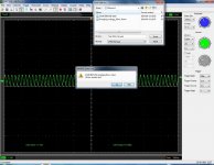
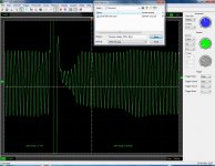
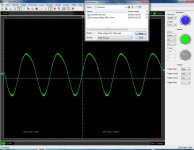
Ok.. Lets try again. Here are the Pictures from my scope , with no load, 8ohm, 16ohm load.
The scope is set to (100ms) for no load and 8 ohm load, in other case it would be impossible to see the "spike" on 8ohm load
What the f... is happening in the midle Picture??? A huge spike followed by almoast no output. I sugest that the output limmiter works just fine... But how does this huge spike apear?? Help Help!!!Ok.. Lets try again. Here are the Pictures from my scope , with no load, 8ohm, 16ohm load.
- Status
- Not open for further replies.
- Home
- Amplifiers
- Solid State
- Help with ocillating amplifier !!