
BF256 is a good replacement too, still in production, it is originally design for hifi amps, available on element 14.Looking at the MPF102 as a replacement for the BF245C. Is there any reason why it would not be a good match?
Here are the datasheets for the two
BF245C - https://www.mouser.com/datasheet/2/308/BF245C-1300109.pdf
MPF102 - https://www.jameco.com/Jameco/Products/ProdDS/26403.pdf
https://www.jameco.com/z/MPF102-Major-Brands-Transistor-MPF102-JFET-N-Channel-TO-92_26403.html
I would suggest you buy a dozen, pick a matched pair, you may need to adjust the trimpot to make the voltage around the midpoint of power supply, about 22V
So I was able to get some NOS BF245C installed. The problem has persisted. Not sure where I messed up in initial troubleshooting, at this point the problem stays with one channel no matter how I swap the transistors.
Going on what @magadeath suggested, I am able to adjust one side to 22V. The other (problem) side hovers around 27V, adjusting the trimpot has no effect on this.
Any suggestions on how to troubleshoot further would be appreciated.
Going on what @magadeath suggested, I am able to adjust one side to 22V. The other (problem) side hovers around 27V, adjusting the trimpot has no effect on this.
Any suggestions on how to troubleshoot further would be appreciated.
Then the transistors are not the problem. Rework all solder joints in the bad channel,
and if that does not help, change the resistors in the bad channel next.
Posting the schematic would help.
and if that does not help, change the resistors in the bad channel next.
Posting the schematic would help.
Then the transistors are not the problem. Rework all solder joints in the bad channel,
and if that does not help, change the resistors in the bad channel next.
Posting the schematic would help.
Will work on that next. Might see if I can identify matching resistors on either side, measure and see if there is any discrepancy. Unfortunately the manufacturer went under. I've reached out to them in the recent past without hearing back, others have reported the same.
Strange. The remedie does not match the diagnose.
Luckily it's a fairly simple circuit. I see these little blue caps just after the big cans. Are these tantalum?
Just guessing, A signal tracer or cooling spray could help.
Hugo
Luckily it's a fairly simple circuit. I see these little blue caps just after the big cans. Are these tantalum?
Just guessing, A signal tracer or cooling spray could help.
Hugo
Strange. The remedie does not match the diagnose.
Think my tests weren't as extensive as they should have been. Anyway, so I put the original transistors back in. I then went to measure some resistors to see maybe one was defective in some capacity. They looked alright, so thought ok next step is to take it home (currently it's in my office) and touch up solder joints. The testing was bugging me, and I did record the noise, wanted to test again to see where I may have failed in my testing. Was silent, no noise. I then opened it up to measure again, the problem side was hovering around 20V, which I could get up to 21.8V with trimpot at max setting. I then took a silicon prodding tool and poked at some the resistors nearby, and sure enough that shot up the value to 25-27V. I think the problem might be a bad solder joint on a resistor as @rayma suggested. Will work on that this weekend and report back.
Last night I touched up all the solder joints on the bottom of the pcb. Was a bit puzzled the bottom didn't have solder pads.. Anyway, put it all back together. Turned it on, adjusted trimpots to get 22V on either side. Let it sit for an hour, again adjusted. Tested it, sounded good, no noise in either channel.
Many thanks to all who helped me troubleshoot this unit. It's a nice headphone and pre amp, hope to get many more years out of it 🙂.
Many thanks to all who helped me troubleshoot this unit. It's a nice headphone and pre amp, hope to get many more years out of it 🙂.
Hi everyone. A question I thought to ask. This amp is definitely doing the job of giving some power, filling out the sound of headphones throughout the spectrum. What I feel is missing is a bit of refinement in its presentation. I think a big part of that is this is how it was designed to sound. But I wonder if replacing any of the capacitors, like the big silver ones, might help a bit in this regard. Or any other mods.. Any thoughts on this? Know it would be difficult to judge purely from pictures, a schematic is unfortunately not attainable. For what it's worth, this amp is likely about 20 years old now. It was considered a top option years before everyone and their grandmother started making headphone amps.
Reverse engineering the schematic should not be too hard, since you can do that from the top.
Give it a try.
Give it a try.
Last edited:
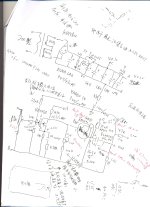
Attached a handscript I had many years ago, notice the res in series with the cap in the source of JFET is 4.7R, not 4.75k. This res should smooth the frequency response of the cap I guess.Hi everyone. A question I thought to ask. This amp is definitely doing the job of giving some power, filling out the sound of headphones throughout the spectrum. What I feel is missing is a bit of refinement in its presentation. I think a big part of that is this is how it was designed to sound. But I wonder if replacing any of the capacitors, like the big silver ones, might help a bit in this regard. Or any other mods.. Any thoughts on this? Know it would be difficult to judge purely from pictures, a schematic is unfortunately not attainable. For what it's worth, this amp is likely about 20 years old now. It was considered a top option years before everyone and their grandmother started making headphone amps.
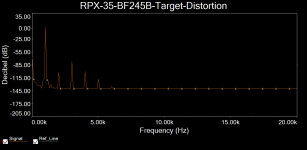
The schem is extremely simple, but opearting point could make a huge difference in distorion. Nelson Pass described this in his article< https://www.passlabs.com/technical_article/the-sweet-spot/>, he called it load line cancellation.
I have made simulation and a prototype, at a very perticular bias point (Mine is 6.8k, at 2.5V), the 2nd harmonic distortion is gone.
Attachments
Last edited:
- Home
- Amplifiers
- Headphone Systems
- Help with noise in one channel of headphone amp