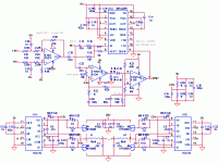
Hello. I got my amplifier going today. It is modulating and everything looks good. I added the LC filter and checked the output, and that's where the problems began. I was sending in a 1Vrms 40Hz sine and getting out a 125kHz sine 12Vpp [rail is 12V for now]. I can see the duty cycle working just like it should so I think that's all ok. However, a couple clues are that the bootstrapped gate signals are only going 0-5V instead of 12V which is the supply for the gate driver. And the lower FET gate signals are only going 0-3.5V, but that's enough to turn them on apparently[?]. There is quite a bit of ripple but I haven't adjusted the gate Rs any, they are 100ohm without antiparallel diodes. The only thing I can think of is that the idle 125kHz square wave is passing thru the LC and getting turned into a sine [upper harmonics chopped off]. However, because I can clearly see the duty cycle change on each of the 4 FETs, that doesn't seem right either. I still have the 4700u caps and antiparallel diodes to add, and the global feedback is not connected, but the rest of the amp is soldered at this point. Could the lack of global feedback make this happen? Any other ideas?
I was using a 10x quality probe and I remember hearing that a series resistor of 1kohm is a good idea to help isolate the probe from switching waveforms. Is this true?
Thank you, Evan
I was using a 10x quality probe and I remember hearing that a series resistor of 1kohm is a good idea to help isolate the probe from switching waveforms. Is this true?
Thank you, Evan
Attachments
I can't edit the above post.....
All measurements were taken with no load connected. The gate signals were all good, going from ~0-12V with no gate R before I connected the FETs. There was ringing but the -overshoot was no worse than ~-4V and the +overshoot didn't surpass ~18V.
Could the lack of a load be the problem?
All measurements were taken with no load connected. The gate signals were all good, going from ~0-12V with no gate R before I connected the FETs. There was ringing but the -overshoot was no worse than ~-4V and the +overshoot didn't surpass ~18V.
Could the lack of a load be the problem?
It turns out I had a 10x probe on the scope but it was the wrong kind and it still attenuated everything by 10. So, I have 0-12V on the lower FET gates and 0-24V on the upper FET gates. Maybe I screwed the bootstrap up somehow? I do not yet have any gate-source diodes but they would just blow since the gate voltage is too high, correct? I don't want to add current limit resistors??
- Status
- Not open for further replies.

