've recently been working on an old Marshall AVT 50. I'm planning to change :
1. Add a 0.68uf cathode bypass capacitor to R29.
2. Replace R32 with a 100k resistor.
These two swaps would increase gain from the 12AX7 .
Then I planned to :
3. Replace R72 with a 33k Resistor.
4. Replace C83 with a 470pf capacitor (treble) and replace C78 (bass) and C79 (mids) with 0.022uf CDE film types.
There is some clipping LED's labeled LED 2, LED 3, LED 5 & LED 6. I was wondering, would it be ok to remove LED 2&3 and replace with jumpers and then replace LED 6 with 1N4007 diode. Then, replace LED 5 with wires going to a On/off/on toggle with a different diode arrangement on the switch? Example being one 1N4007 in the middle, two 1N4007 up, and a LED for the down position?
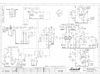
For the record, I am aware amps contain high voltage. I am safe, and take all precautions while working inside the amp. I have provided a schematic of the preamp section for reference
1. Add a 0.68uf cathode bypass capacitor to R29.
2. Replace R32 with a 100k resistor.
These two swaps would increase gain from the 12AX7 .
Then I planned to :
3. Replace R72 with a 33k Resistor.
4. Replace C83 with a 470pf capacitor (treble) and replace C78 (bass) and C79 (mids) with 0.022uf CDE film types.
There is some clipping LED's labeled LED 2, LED 3, LED 5 & LED 6. I was wondering, would it be ok to remove LED 2&3 and replace with jumpers and then replace LED 6 with 1N4007 diode. Then, replace LED 5 with wires going to a On/off/on toggle with a different diode arrangement on the switch? Example being one 1N4007 in the middle, two 1N4007 up, and a LED for the down position?
For the record, I am aware amps contain high voltage. I am safe, and take all precautions while working inside the amp. I have provided a schematic of the preamp section for reference
Attachments
Thank you, I'll get something closer to that value. I'm just wanting to increase the gain from the tube a little, and also clean up some of the diode clipping in the clipping circuit by removing LED 2 & LED 3. I'd be ok replacing those with jumpers and removing them?For a 1k cathode bypass, you need more like 10uF.
Smaller values of the C will reduce the bass range.
If defeating the clipping circuit, just remove the LEDs, but no jumpers.
If defeating the clipping circuit, just remove the LEDs, but no jumpers.
Smaller values of the C will reduce the bass range.
If defeating the clipping circuit, just remove the LEDs, but no jumpers.
I've changed my drawing. I'm going to use a parallel 10uf as a cathode bypass and I've removed the LED's completely.
Any other tips on getting a little more gain and response from the single 12ax7?
I've sapped the LED 5 & LED 6 for a clipping circuit on a toggle using 1N4007 diodes. That way I can remove it if I choose.
Notice the 1.5k series and 1.5k shunt resistors at the input of the first 12AX7 section.
You will have 6dB more gain by increasing only the shunt 1.5k resistor to at least 20k,
but preferably use 100k to keep the bass from rolling off due to the input 2.2uF capacitor.
You will have 6dB more gain by increasing only the shunt 1.5k resistor to at least 20k,
but preferably use 100k to keep the bass from rolling off due to the input 2.2uF capacitor.
Smaller values of the C will reduce the bass range.
If defeating the clipping circuit, just remove the LEDs, but no jumpers.
I've changed my drawing. I'm going to use a parallel 10uf as a cathode bypass and I've removed the LED's completely.
Any other tips on getting a little more gain and response from the single 12ax7?
I've sapped the LED 5 & LED 6 for a clipping circuit on a toggle using 1N That way I can remove it if I choose.
Notice the 1.5k series and 1.5k shunt resistors at the input of the first 12AX7 section.
You will have 6dB more gain by increasing only the shunt 1.5k resistor to at least 20k,
but preferably use 100k to keep the bass from rolling off due to the input 2.2uF capacitor.
So changed R30 to 100k and use atleast a 10uF bypass capacitor on R29?
Right.
Of course you can also bypass R33 the same way, for extra gain.
I plan on bypassing both cathodes. What would recommend to correctly remove LED 2 & LED 3 from thr back side on the O/D volume? I want to remove some of the diode clipping to make the distortion not so harsh. If I want clipping I'd prefer to do it after the tube at LED 5 & LED 6.
Yes, just remove the LEDs completely.
I Will remove LED 2 & LED 3. With the additional gain from the 12ax7 stage the loss from changing LED 5 & LED 6 to a 1N4007 style asymmetrical clipping circuit should be negligible I'd assume, no?
If I had an asymmetrical clipper (two 1n4007 on one side and 3 on the other) my loss wouldn't be as much no?
Right, each diode adds around 0.6V peak. Three in series would be close to an LED.
I plan on doing 3 diodes on one side, then the other side I'll connects wires to a toggle that'll have 2 diodes in the up position, 1 red LED in the middle and 3 diodes in the down position.
Any other tips? I've already ordered Mojotone Dijon caps to replace all caps in the signal Path except for the electrolytics.
Apparently LED 2 & LED 3 allow the signal gain to be set by the resistor and variable resistor, but then reduce the gain when the signal hits around 1.5V peak. So I couldn't remove them because then the op amp wouldn't amplify at all?
I'd only do one change at a time, so if something goes wrong, you'll know where the problem is.I plan on doing 3 diodes on one side, then the other side I'll connects wires to a toggle that'll have 2 diodes in the up position, 1 red LED in the middle and 3 diodes in the down position. Any other tips? I've already ordered Mojotone Dijon caps to replace all caps in the signal Path except for the electrolytics.
Not sure how that works, the diodes do need 2V to conduct at all, independent of the gain.Apparently LED 2 & LED 3 allow the signal gain to be set by the resistor and variable resistor, but then reduce the gain when the signal hits around 1.5V peak. So I couldn't remove them because then the op amp wouldn't amplify at all?
0.68u has provenance. Guitar can be boomy and fail to cut past the kick and bass. Marshall "studied" Fender's work but used 0.68uFd at one cathode. This caused a ~~6dB "shelf" between bass and mids. Less power was put to rumble, more power to "scream". (Also interactions with the UK speakers, the closed-back box, and the increased NFB.)For a 1k cathode bypass, you need more like 10uF.
The wise builder will not cast these parts in stone until an extended break-in and playing session.
Well, in AVT the earlier solid-state gain stages are already employed for emphasizing treble boost. We don't neccessarily need to mimick a 2203 here.
It would of course help the discussion if OP told us what he is trying to achieve with the modifications. E.g Cut LEDs off just for the sake of it...? Big deal, the following grid is going to clip around 1.5V anyway, the opamp now probably clips to rails and the LED clamping probably just makes the circuit behave better under greater amounts of overdrive anyway.
In AVT series Marshall at least really did introduce real tube clipping (no local NFB to limit stage gains to <10 like in JCM900 DR's and earlier Valvestate amps). They even went on to "starve" the B+ to around 100VDC to promote clipping of the tube stages even more effectively.
- Home
- Live Sound
- Instruments and Amps
- Help with mods