I am a total electronic ignoramus.
I am building an active mixer (virtual earth) using a MCP6271 Rail-to-Rail Op Amp . (Please see attached circuits diagram). This is being used mix two "True line-level stereo outputs: 2.1V RMS ground centered, 100dB SNR" together for a mono output.
I have wired the circuit exactly as per the diagram (no more or less) with a 5v supply , this does work but with a distorted output.
I need help with suggestions for the extra components I need to add in the way of resistors and capacitors to make this work
Can you keep this simple please.
Many thanks
Attachments
Welcome here!
Are you using a single 5V supply ?
If yes, do you connect IC pin 4 to GND and IC pin 8 to V+ ?
You have to bias pin 3 (the -In) to V+/2.
How?
Connect two 100kOhm resistors is series btn 5V and GND. Then connect IC pin 3 at the mid of the two resistors.
Then connect a DC blocking capacitor in series with the output (a 10uF electrolytic with the + to IC pin 1)
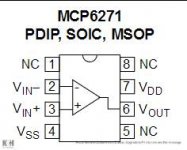
>Edit. The IC pin numbers refer to your diagram with the TL072. Check what pin is what with your MCP6271 (pin function changes with package type)
George
Are you using a single 5V supply ?
If yes, do you connect IC pin 4 to GND and IC pin 8 to V+ ?
You have to bias pin 3 (the -In) to V+/2.
How?
Connect two 100kOhm resistors is series btn 5V and GND. Then connect IC pin 3 at the mid of the two resistors.
Then connect a DC blocking capacitor in series with the output (a 10uF electrolytic with the + to IC pin 1)
>Edit. The IC pin numbers refer to your diagram with the TL072. Check what pin is what with your MCP6271 (pin function changes with package type)
George
Hi George,
many thanks for your reply.
Just to check on your information :
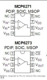
I have attached the pins diagram for the MCP6271 op amp and the TLO72.
To clarify you say " [/B]bias pin 3 (the -In) to V+/2" referring to the diagram of the TL072 . Do you not mean the invert - i/p 2 ?
Finally how can I achieve a output of : 2.1V RMS ?
Cheers
Sam
many thanks for your reply.
Just to check on your information :
I have attached the pins diagram for the MCP6271 op amp and the TLO72.
To clarify you say " [/B]bias pin 3 (the -In) to V+/2" referring to the diagram of the TL072 . Do you not mean the invert - i/p 2 ?
Finally how can I achieve a output of : 2.1V RMS ?
Cheers
Sam
Attachments
Last edited by a moderator:
Connect two 100kOhm resistors is series btn 5V and GND. Then connect IC pin 3 at the mid of the two resistors.
Then connect a DC blocking capacitor in series with the output (a 10uF electrolytic with the + to IC pin 1)
This won't work properly. Bias the + input to Vcc/2, and add a 10uF blocking cap after the mixing resistors
(but before the input pin or feedback resistor), as well as another one at the output.
Last edited:
Many thanks to you all for your replies, they have high lighted where I have gone wrong with my simplistic interpretation of the diagrams.
I will rewire the preamp as per the attached circuit diagram.
Cheers Sam
I will rewire the preamp as per the attached circuit diagram.
Cheers Sam
Hi 142victoria
Do as rayma correctly points out. (see schematic below).
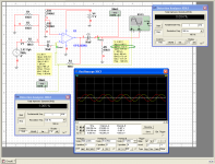
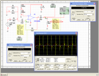
I simulated the circuit using OPA342 (the Burr Brown’s equivalent to your MCP6271) and I see that for undistorted output your max input and output signal (the gain is x1) can not exceed 1.8Vrms.
The reason for this is that the IC output can not swing above the 5V, your power supply dc voltage.
There are 2.5Vdc at the output, so what remains for the AC swing to top the output to 5V is 2.5Vp which is 1.8Vrms 🙂
As for the value of the DC blocking capacitors, with 10uF the low frequency –3dB point is at 5Hz. That’s a bit high.
If you make them 47uF the low frequency –3dB point goes down to 1Hz.
If you make them 100uF the low frequency –3dB point goes down to 0.5Hz.
George
Do as rayma correctly points out. (see schematic below).
I simulated the circuit using OPA342 (the Burr Brown’s equivalent to your MCP6271) and I see that for undistorted output your max input and output signal (the gain is x1) can not exceed 1.8Vrms.
The reason for this is that the IC output can not swing above the 5V, your power supply dc voltage.
There are 2.5Vdc at the output, so what remains for the AC swing to top the output to 5V is 2.5Vp which is 1.8Vrms 🙂
As for the value of the DC blocking capacitors, with 10uF the low frequency –3dB point is at 5Hz. That’s a bit high.
If you make them 47uF the low frequency –3dB point goes down to 1Hz.
If you make them 100uF the low frequency –3dB point goes down to 0.5Hz.
George
Attachments
I am a total electronic ignoramus.
I am building an active mixer (virtual earth) using a MCP6271 Rail-to-Rail Op Amp . (Please see attached circuits diagram). This is being used mix two "True line-level stereo outputs: 2.1V RMS ground centered, 100dB SNR" together for a mono output.
I have wired the circuit exactly as per the diagram (no more or less) with a 5v supply , this does work but with a distorted output.
Finally how can I achieve a output of : 2.1V RMS ?
You simply can´t.
2.1V RMS means 5.92Vpp or 6V supply which you don't have. End of the story.
Lower your expectations or rise suppy voltage.
Wow thank you again George for you very generous effort on my behalf ;
I will today finish of the mixer preamp using 100uf capacitors as suggested.
The software program that you used for your analyse is most impressive ,can I assume that the program was Multsim student ?
Hi Fahey I can see that using the 5v supply will result in a output less than the original sources ,I think I can live with this. By the way you may be interested that this mixer is being used for a midi Hurdy Gurdy using an optical encoder for handle turn inf. and a ribbon pot on the keys. All into an Arduino playing wav files on "WAV TRIGGER"s
Sam
can I assume that the program was Multsim student ?
Anything from Electronic WorkBench (EWB) 5 and above has all the virtual test instruments you will need for this hobby.
Then EWB went on developing under the name Multisim, then under National Instruments (NI) Multisim.
All these have just a few more bells and whistles e.g. exporting the test data (for further analysis by a spreadsheet)
Currently (until July 2017) there is a free Mouser version available for download:
http://eu.mouser.com/MultiSimBlue/
(I’ve tried it. It works OK)
Read the pros and cons here
MultiSIM BLUE Review » PCBShopper
George
Hi all ,
having wired the MCP6271 as per your suggestions, I am sorry to report that the output would seem to sound loud and clear, if it was not for the awful frying egg noises , motor boating ,plus whistles when led`s are switching on and off and from the optical rotary encoder when turned.
Some of the noise is coming from the supply (I tested the amp with a independant power supply) .
The funny thing is that the mixed signals of the mixer without a op amp produces an output with a very much better noise to sound ratio,( any screening being the same in both cases).
Any ideas ?
Sam
Perhaps I might have an answer to my problem .
On closer inspection I see I have been sold a MCP6273 with a CS (chip select) pin. (see attached diagram). The spec sheet says quote
"MCP6273/5 Chip Select (CS)
The MCP6273 are single op amps with Chip Select (CS), . When CS is pulled high, the supply current drops to 0.7 μA (typ.) and flows through the CS pin to VSS. When this happens, the amplifier output is put into a high-impedance state. By pulling CS low, the amplifier is enabled. If the CS pin is left floating, the amplifier may not operate properly."
So if I tie the CS pin to earth the noise problem might go away?
I will give this a go tomorrow.
Cheers Sam
Attachments
I am ready to throw the towel in. The amp amplifies but with so much noise.
As stated I have wired the op-amp as sugested by George and Tayma .
Am I in need of more blocking capacitors some where ,or what ?
Please help
Sam
As stated I have wired the op-amp as sugested by George and Tayma .
Am I in need of more blocking capacitors some where ,or what ?
Please help
Sam
You've had all the right advice... does your circuit now look like the one George posted ?
You need the input and output AC coupled as shown. You may need a small cap (say 10uf)across R12 in George's diagram to decouple the reference voltage.
Always check the DC voltages. Pins 2,3 and 6 should all be at around one half the supply voltage.
You may need a series resistor of say 100 ohm at the output to isolate the output from any significant stray capacitance.
You have to sweat a bit, that’s how you’ll enjoy the outcome.🙂
Can you describe the power supply you use?
The IC datasheet suggests a 0.1uF cap directly across pins 4 -7 . The larger bupass capacitor >10uF can be placed a bit further.
http://ww1.microchip.com/downloads/en/DeviceDoc/21810f.pdf
If the noises are as strong and of the kind you describe in post #10, I think something else is going on.
Are your input & output cables shielded? Where do you connect the shields?
I would suggest to start the troubleshooting by removing all the input components and all the input wiring.
Remove everything upstream of input capacitor (C2) and solder a 10k resistor across the left pin of C2 and ground.
If the output is quiet with this configuration, the IC circuit is OK.
Then remove this 10k resistor and start reconnecting one branch of the input each time.
You will spot the noisy input.
George
Thank you for your reply George. I will try your suggestions as soon as I can find the play time.
As yet I can not get this amp to work . This to me seems very weird as the output of the mixer before the op amp gives a clean signal , very little noise associated from lack of screening.
The mixer purpose is to mix two left and two right channel wav files to a mono output large enough to drive on board headphones as well as provide an output to an external amp.
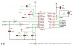
The signal sources to the four input mixer are two PCM5102 stereo digital-to-analog converters, providing each a left and right 2.1VRMS ground centred output, (allowing designers to eliminate DC blocking capacitors on the output). I have attached a diagram of the DA converter as on the wav player.
I hope this information is of help.
Sam
As yet I can not get this amp to work . This to me seems very weird as the output of the mixer before the op amp gives a clean signal , very little noise associated from lack of screening.
The mixer purpose is to mix two left and two right channel wav files to a mono output large enough to drive on board headphones as well as provide an output to an external amp.
The signal sources to the four input mixer are two PCM5102 stereo digital-to-analog converters, providing each a left and right 2.1VRMS ground centred output, (allowing designers to eliminate DC blocking capacitors on the output). I have attached a diagram of the DA converter as on the wav player.
I hope this information is of help.
Sam
Attachments
The amp amplifies but with so much noise.
If you have followed the schematic from post #6, I'm not surprised. The virtual ground arrangement is quite sensitive to power supply noise as shown. Add a small electrolytic across (his) R12, i.e. from +in to ground, preferably near the chip - polarity observing, of course, 10µF-ish would do.
Problem solved but more help needed
Thank you all for your help.
Stephen was correct in the last post;
The problem was solved, (all most), with the capacitor from the VIN+ to ground.
There is still a fair amount of frying egg noise. The inverting amp is obviously very sensitive to noise, I will rewire my project with more attention to screening.
I now would like a new problem solved; Please see attached diagrams.
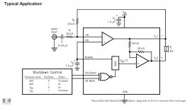
In my quest for a mixer signal restoration amp I took the mixed un- amplified signal and fed it into the hacked input ( this originally had a single left ear input connected ) of an on board speaker amp LM4990 on the Wav Trigger. This produces a very good signal ( I know it is not a virtual earth amp but could solve a lot of problems ).
How can I couple the output of the LM4990 to the input of a small single supply TDA2030A ebay Power Amp to be use on board in my project (the output and input do not seem compatible as configured)??
Sam
Thank you all for your help.
Stephen was correct in the last post;
The problem was solved, (all most), with the capacitor from the VIN+ to ground.
There is still a fair amount of frying egg noise. The inverting amp is obviously very sensitive to noise, I will rewire my project with more attention to screening.
I now would like a new problem solved; Please see attached diagrams.
In my quest for a mixer signal restoration amp I took the mixed un- amplified signal and fed it into the hacked input ( this originally had a single left ear input connected ) of an on board speaker amp LM4990 on the Wav Trigger. This produces a very good signal ( I know it is not a virtual earth amp but could solve a lot of problems ).
How can I couple the output of the LM4990 to the input of a small single supply TDA2030A ebay Power Amp to be use on board in my project (the output and input do not seem compatible as configured)??
Sam
Attachments

- Status
- Not open for further replies.
- Home
- Source & Line
- Analog Line Level
- Help with mixer using MCP6271 op amp