I just pulled my Cambridge Audio Azur 540A out after 4 months of non-use. It has developed a nasty channel imbalance. I have verified that the source and speakers are not the culprits. It sounds pretty good when I adjust the balance knob but I believe part of the output stage has become damaged.
I'm a third year EE student and have built some DIY projects such as headphone amps, DACs and regulated power supplies and this amp is out of warranty so I figured I'd see if I could fix it.
I have been unable to locate a service manual online, does anyone know where I can find one?
Also, does anyone have a suggestion what specific parts may be bad?
Thank you,
Justin
Hi,
Damaged power amplifiers tend to not work at all.
I'd check switches, potentiometers and connections first.
🙂/sreten.
Damaged power amplifiers tend to not work at all.
I'd check switches, potentiometers and connections first.
🙂/sreten.
Thanks.
Yeah I was trying to think what would just cause a channel imbalance. I've switched inputs to verify that it wasn't a problem with just my CD input. I've switched over to the B speaker outs, though that doesn't help much since they are internally connected to the same point.
How should I check the pot? Just test the resistance across it is equal for both channels?
Test the signal coming from the pre-out socket for the same imbalance. If it's imbalanced there, the fault is in the pre-amp stage, and the most likely culprit is the pot.
You are correct - simply check the resistance measurements on both tracks of the pot.
You are correct - simply check the resistance measurements on both tracks of the pot.
Looks like the problem is the pot. I tested the pot resistance on both channels. At first I only noticed a small difference, but then I remembered it was an audio-taper pot so small difference at normal levels can be bad.
I picked a data point right around normal listening level to test:
At 9 o-clock on the dial, the right channel resistance measured 17.13 k-ohms and the left channel resistance was 17.01 k-ohms. It seemed close enough to me, but then I realized that I needed to increase the volume to about 11:30 to get the right channel resistance down to the value the left channel had at 9 o-clock.
Hi I'm looking for service manual for my Cambridge Audio 540A integrated amplifier.
I have service manual for for 540A v2, but need for 540A.
Planning to upgrade OP AMS, potentiometers and caps, same way as I have done on 640C v2, have a manual if any body interesting.
Hope for your advice.
sasha@ireland.com
Thanks.
I have service manual for for 540A v2, but need for 540A.
Planning to upgrade OP AMS, potentiometers and caps, same way as I have done on 640C v2, have a manual if any body interesting.
Hope for your advice.
sasha@ireland.com
Thanks.
Hi I have downloaded service manual for CA 640A and so far this look exactly same as CA 540A, can't see any differences. Price?
Looking for advice:
Double capacitors 47U and 10N in parallel in signal path, what is the reason for them?
Can I bypass them with a piece of wire?
Regards. Sasha.🙂
Looking for advice:
Double capacitors 47U and 10N in parallel in signal path, what is the reason for them?
Can I bypass them with a piece of wire?
Regards. Sasha.🙂
Attachments
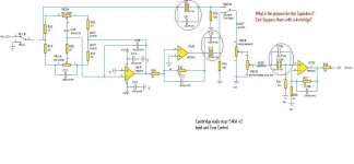
Reason is to block any DC offset from the NE5532 opamps. If you use low offset output opamps such as something FET based like OPA2134, you can bypass them.
 Kjozsi - the material you posted was clearly marked as copyrighted, complete with a statement that the material may not be copied, retransmitted, or otherwise disseminated without the permission of Cambridge Audio. Such materials may not be posted here.
You may hand copy the original schematics or redraw them, and post your interpretation of their instructions with questions. Note any quotes.
Please do not do this again. (Next time will get you an infraction)
Protection mode Azur 540a V2
Hello everybody,
I have a problem with my Azur 540a V2. When the amp is switched on, at once the protection LED constantly flashes in single bursts.
How I can find the really fault, when the protection mode takes part at once?
Anyone an idea, why this protection mode is activated?
The manual describes a problem like high DC voltage ...
I beg your pardon for my english
best regards
Wolfgang
Hi Fried I have the same problem the cambridge audio support is ****, I never advice to buy this ****. Used cheap Pic IC to do protection and if any small variation it goes to protection. They dont like to give the manual
Whats wrong with using a PIC exactly? The PIC doesn't actually do the protection detect - that is done by discrete circuitry.
A frequent problem on the CA amps is the SAP15 transistors failing due to inadequate heatsinking and the vulnerability of the on-die ballast resistor. The latter problem is why Sanken discontinued the parts.
A frequent problem on the CA amps is the SAP15 transistors failing due to inadequate heatsinking and the vulnerability of the on-die ballast resistor. The latter problem is why Sanken discontinued the parts.
Solved the issue.
Gents hours of strugling I was able to run the unit. What I did. on the pcb near 230/110 V plug you have protection relay that cut the power to power amp. I cut the cable and connected directly orange to orange yellow to yellow.
So I feed direct but be carefully check is any DC output on ur speaker my amp no DC . This **** protection says its DC on speaker out. Now its runnig all ok.
I have noticed most of the modern amplifiers stupid protection circuits create more problems. If need more help pls contact I will explain how I by pass and make my 550A make work😀
Repair the amplifier.protection relay that cut the power to power amp
Disabling the detection of errors, or disabling the protection is not repairing the amplifier.
As the protection works fine from the factory, it is not "stupid". If it is tripping, there is something wrong with the circuit. The protection circuits monitor more than just DC offset by the looks of it. Assuming there's no fault because there's no DC is stupid.
The risk is yours, if a fault that occurs in the amp, it will be your funeral when it takes out your speakers.
The risk is yours, if a fault that occurs in the amp, it will be your funeral when it takes out your speakers.
Incidentally, if you bothered to look at the schematic you would see CN7 on the main amp PCB. This is where the protection circuitry connects to the PIC, and each error has its own pin. You could easily have found out what error is being detected to investigate further.
The PIC only shuts off the power because it is *told to* by the protect circuits.
The PIC only shuts off the power because it is *told to* by the protect circuits.
- Status
- Not open for further replies.
- Home
- Amplifiers
- Solid State
- Help with mis-behaving Cambridge 540A