I have been trying to design a 3 way MEH, so far I have built a prototype with a 3d printed throat and MDF horn.
I have been measuring and adjusting different things but can't get it over 900hz.
I modelled it in Akabak with the front chambes in LEM then the ports and horn in BEM


My BEM sim in Akabak goes up to 2khz (Red is sim, Blue is measured) but in reality it drops off above 900hz ish


For the drivers I am using four B&C 4NDF34 I have modelled and printed pieces to make them closed back and reduce the rear volume to 0.1L each.
The tape was temporary to hold the rear chamber pieces, I have hot glued the back pieces onto a single driver and am just measuring one at the moment. I did measure with them taped on and there wasn't much difference.
I have measured the impedence of the drivers and compared them to a sim with just a 0.1L rear chamber and the impedence peak is in the same place so I think I have got that part correct. I got a 3d drawing from B&C and modelled it on that to work out the rear volume.

The below is my last measurement: (I didn't save it so don't have the data to make a proper graph)

I have tried adjusting the tap length and front chamber volume but not managed to get it any higher.
The area at the taps is ~19.33 cm^2 and they are 3.5cm away from the compression driver which makes me think they should be able to play above 900hz easily
Currently the compression ratio is a bit high so I am tempted to forget about going above 900hz and move the mid drivers further away from the comp.
Has anyone got any advice for how I could get the mids to go a bit higher?
I have been measuring and adjusting different things but can't get it over 900hz.
I modelled it in Akabak with the front chambes in LEM then the ports and horn in BEM
My BEM sim in Akabak goes up to 2khz (Red is sim, Blue is measured) but in reality it drops off above 900hz ish
For the drivers I am using four B&C 4NDF34 I have modelled and printed pieces to make them closed back and reduce the rear volume to 0.1L each.
The tape was temporary to hold the rear chamber pieces, I have hot glued the back pieces onto a single driver and am just measuring one at the moment. I did measure with them taped on and there wasn't much difference.
I have measured the impedence of the drivers and compared them to a sim with just a 0.1L rear chamber and the impedence peak is in the same place so I think I have got that part correct. I got a 3d drawing from B&C and modelled it on that to work out the rear volume.
The below is my last measurement: (I didn't save it so don't have the data to make a proper graph)
I have tried adjusting the tap length and front chamber volume but not managed to get it any higher.
The area at the taps is ~19.33 cm^2 and they are 3.5cm away from the compression driver which makes me think they should be able to play above 900hz easily
Currently the compression ratio is a bit high so I am tempted to forget about going above 900hz and move the mid drivers further away from the comp.
Has anyone got any advice for how I could get the mids to go a bit higher?
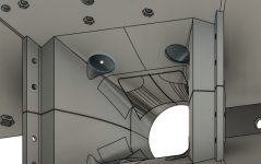
the extreme tap location at the edge of the cone?
344/127e-3/3 = 902Hz so acoustic path length difference from the far edge of the cone is causing cancellation. This position is not a good idea as well due to pressure on the diaphragm.
344/127e-3/3 = 902Hz so acoustic path length difference from the far edge of the cone is causing cancellation. This position is not a good idea as well due to pressure on the diaphragm.

ahh, thanks! that is a good point.
I was looking at some of the danley MEH and they have the taps right at the edge although I'm not sure how high they play because the taps are quite far down the horn and far apart.
I will try printing a test piece with the tap more central
I was looking at some of the danley MEH and they have the taps right at the edge although I'm not sure how high they play because the taps are quite far down the horn and far apart.
I will try printing a test piece with the tap more central
Hi, i'm using that driver with a single port per driver, 2cm in dia, and 7.75cm from CD flange. Ports are in the corners, but I doubt it matters too much.
The port hole center is located roughly over where the driver's dust cap meets cone...so more towards the driver's center.
And I didn't reduce volume between cone and horn any..
They are open back...no rear chamber and not even inside a surrounding box....an open baffle/ syn hybrid lol
I say all that because I don't know why you're getting such a steep falloff at 900Hz. Maybe kipman725 has it sorted...
My first suggestion would have been to reduce volume between the cone and horn wall, but you've already done that to the max ...maybe too much so???
My second suggestion is remove the closed back, just to see.
Oh, and what's the diameter of your ports... I'm not understanding 19.33 cm2 area, which seems very large vs the pictures...
Here's the response of my mids as described above, .....if it helps. The green trace is them.
for future ideas what about 3D printing a single slot phase plug (ring) turning it into a midrange compression driver and using this idea? https://www.diyaudio.com/community/...per-scripts-and-m200-fun.385493/#post-7009215
Maybe you also have a leak somewhere? It is a good idea to seal the 3D printed surfaces with a layer or two of acrylic spray paint - I always do that. But my bet would be definitely on the hole being too close to the edge of the cone. Here are my trials with 3FE22s - put into holes originally meant for a single 8" - https://www.diyaudio.com/community/threads/2-way-synergy-inspired-by-spl-runt.378456/post-6906321
I am printing a test piece but then I think I'm gonna redesign it to better balance the distance from the comp and not aim so high. I think I will be able to get 1.5khz out of it with 4 drivers still.

I have kept the taps the same diameter but there is two and they are much longer so hopefully it balances out. I did some quick sims in hornresp. It's gonna take two hours to print so I should have some more measurements today.
I have kept the taps the same diameter but there is two and they are much longer so hopefully it balances out. I did some quick sims in hornresp. It's gonna take two hours to print so I should have some more measurements today.
My taps are 15mm in diameter. That area is the area of the horn at the point the taps enter.Hi, i'm using that driver with a single port per driver, 2cm in dia, and 7.75cm from CD flange. Ports are in the corners, but I doubt it matters too much.
The port hole center is located roughly over where the driver's dust cap meets cone...so more towards the driver's center.
And I didn't reduce volume between cone and horn any..
They are open back...no rear chamber and not even inside a surrounding box....an open baffle/ syn hybrid lol
I say all that because I don't know why you're getting such a steep falloff at 900Hz. Maybe kipman725 has it sorted...
My first suggestion would have been to reduce volume between the cone and horn wall, but you've already done that to the max ...maybe too much so???
My second suggestion is remove the closed back, just to see.
Oh, and what's the diameter of your ports... I'm not understanding 19.33 cm2 area, which seems very large vs the pictures...
Here's the response of my mids as described above, .....if it helps. The green trace is them.
View attachment 1153190
the extreme tap location at the edge of the cone?
344/127e-3/3 = 902Hz so acoustic path length difference from the far edge of the cone is causing cancellation. This position is not a good idea as well due to pressure on the diaphragm.
I agree. When you have unequal pathlengths it screws up the response. Those taps are basically a phase plug, and the last thing you want in a phase plug is unequal distances.
Your midrange taps are too close to the throat. In the Danley SH-50, each midrange tap is 38mm in diameter and they're located 89mm from the apex of the horn.
Hi, I dunno about ports being near the edge of a cone to be a problem.I agree. When you have unequal pathlengths it screws up the response. Those taps are basically a phase plug, and the last thing you want in a phase plug is unequal distances.
Here's a photo of a SH-50 with Misco mids. The ports are clearly pushed out from center.

Yep, OP's ports are unusually close to throat. I've been wanting to try that...I'm kinda thinking it might be a good thing. But I've only played with using mid drivers on a few builds. I don't have experience with them, as much as taking a CD straight to a large low-mid driver.Your midrange taps are too close to the throat. In the Danley SH-50, each midrange tap is 38mm in diameter and they're located 89mm from the apex of the horn.
I'm puzzled......38mm dia seems awfully large, both vs the above pict and on this one of the SH-50 throat. typo maybe? 89mm from apex seems on target....

I have redesigned it a bit and moved them away from the throat.
I was originally aiming for 2khz before rolling off which meant I needed to have them that close to get the cross sectional area small enough. I think I was attempting to not comprimse somewhere though by also having a large vertical dispertion to get a large mouth. I am aiming to have four 12" drivers as well and have simmed those down to 60hz.


I am printing some pieces out overnight so will hopefully measure them tomorrow
I was originally aiming for 2khz before rolling off which meant I needed to have them that close to get the cross sectional area small enough. I think I was attempting to not comprimse somewhere though by also having a large vertical dispertion to get a large mouth. I am aiming to have four 12" drivers as well and have simmed those down to 60hz.
I am printing some pieces out overnight so will hopefully measure them tomorrow
Attachments
I made the tap slightly bigger and it seems like I'm getting a cancellation at 1.135khz now. I'm gonna do some more testing

what about a slot shaped tap? it looks like you could reduce the maximum distance from the center of the driver cone using a slot.
although I am a bit perplexed if 10" drivers can do this:

https://www.diyaudio.com/community/...single-point-source-horn.264485/#post-4114406
why your drivers are stuggling so much.
Are you gating your measurements? doing so should clean up the data a bit
Also are you able to measure the T/S parameters of your drivers?
Also as a sanity check can you remove your compression driver and tape over the throat? the phase plug looks like an anular ring driver and apart from the coaxial comps that cross super low, these are not common to use in MEH.
I'd just leave out all the printed volume filler, between the driver's cone and the horn wall.
That's my first choice guess as to the problem....
That's my first choice guess as to the problem....
The peak at 800 followed by the dip at 1135 suggest that the ratio port area to length is off. It should ideally be a smooth roll-off.
- Home
- Loudspeakers
- Multi-Way
- Help with MEH getting over 900Hz