My 10 years old McCormack DNA 0.5 amp (regular not upgraded) sends a really loud buzz to the speakers the moment it's turned on. After that, the power indicator led goes from red to green and everything seems to be working. The loud buzz happens even when nothing is connected to the input.
Mr. McCormack was very nice to provide me with a schematic of the amp. The problem is my electronic experience is only limit to kit building and such.
So I send my amp to a local shop. They told me the problem is caused by a surface mount chip so it can not be repaired. The total cost for replacing the main board is close to $400! Maybe I am wrong but I didn't see any surface mount chip in the amp when I open the cover. Plus, I have replaced surface mount chip myself before so I just dropped the diagnostic cost and walked out of the door.
Can anyone help me identify the capacitors and transistors to check? Due to potential copyright issue I am not sure I should post the diagram here, but maybe through email? Thanks.
TY
You could start with simple things like power supply voltages.
Check for DC on output with no signal in.
Check for DC on output with no signal in.
Thanks for the reply. There is a 0.5 to 0.8 V spike at the speaker terminals the moment the power is turned on. The voltage then drop back to close to 0 as the led turning from red to green. I should mention the loud buzz is also transient, just like the voltage spike.
'Seems to me that protection circuits usually isolate the speakers until the amp. has stabilized. i.e. after the voltage spike has passed. If you hear that noise first up, is there a relay that clicks at some point?
Possibly, the protection circuit is only a VI limiter circuit that doesn't directly protect the speakers but the fact that the LED changes at approximately the right interval suggests a delayed switch-on there somewhere and it should be to the speakers. this control is often by microcontroller in modern products.
Possibly, the protection circuit is only a VI limiter circuit that doesn't directly protect the speakers but the fact that the LED changes at approximately the right interval suggests a delayed switch-on there somewhere and it should be to the speakers. this control is often by microcontroller in modern products.
Yes. I can hear a click right around when the led turns from red to green. That happens several seconds after the initial buzz/voltage spike. According to the diagram, there is a DS2YE-S-DC24V relay. I didn't see any big chip on top of the circuit board. Mr. McCormack did mention that the problem could be a transistor or capacitor.
The "big chip" can be just an insignificant 8 pin SMD on the copper side, though I doubt that from the age of the amplifier. You should be able to identify a micro. as a rectangular block on the schematic - protection circuit block, if one is there.
So, the relay clicks but it's only a miniature Panasonic type, max. 3A current, rated to 250VAC but not heavy enough to switch speaker output leads. This is likely a muting relay or DC control circuit holding off the input, or perhaps disabling the output stage rather than a speaker relay. Otherwise, how do you get to hear the noise of the amplifier turn-on before the relay pulls in? I would take a look at your schematic, to satisfy yourself what the relay does and kindly advise us so we can help. If you can't do that, its going to be hard to advise what to do unless we also have a McCormack amplifier or access to the IP.
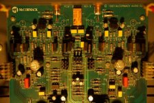
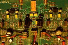
You could take high-res. pics of both sides of the board, centred around the relay and output stage without specifically divulging circuit details or the schematic. Post them here and some, like service techs who are practiced in fault finding, may be able to offer their experienced help.
So, the relay clicks but it's only a miniature Panasonic type, max. 3A current, rated to 250VAC but not heavy enough to switch speaker output leads. This is likely a muting relay or DC control circuit holding off the input, or perhaps disabling the output stage rather than a speaker relay. Otherwise, how do you get to hear the noise of the amplifier turn-on before the relay pulls in? I would take a look at your schematic, to satisfy yourself what the relay does and kindly advise us so we can help. If you can't do that, its going to be hard to advise what to do unless we also have a McCormack amplifier or access to the IP.
You could take high-res. pics of both sides of the board, centred around the relay and output stage without specifically divulging circuit details or the schematic. Post them here and some, like service techs who are practiced in fault finding, may be able to offer their experienced help.
The only rectangular I can find in the diagram is in the power supply section, power regulator LM317 and LM337. There are areas labeled as "rail voltage sensors" and "integrator" on the driver PCB. Should those 2 areas be the focus of interest? I am wondering if the damage was done by my accidentally turned off the Meridian front end before the amp in the past (which triggered the protection circuit).
It was close to midnight when I saw your post last night so I only took pictures from the top. Judging by how close the RCA input and relay are located on the circuit board, I think you are right about the relay is used to mute the input.
TY
It was close to midnight when I saw your post last night so I only took pictures from the top. Judging by how close the RCA input and relay are located on the circuit board, I think you are right about the relay is used to mute the input.
An externally hosted image should be here but it was not working when we last tested it.
TY
I can't load your image so I guess you may need moderator help or go over the pic. attaching advice again.
Also, since we are learning a little about the relay, you could measure voltage to ground (there should be a convenient ground point near the relay or even the speaker ground will do) from the pins that are NC, COM, NO. Just one channel or side of the relay will do. That is: Normally closed, Common and Normally open poles, as any simple 2-way switch could be described. It's usually marked on the relay body.
If there are no heavy PCB traces and no DC is present anywhere other than the 24V coil connections when the relay is powered, you can assume this is a signal level relay.
Image upload advice from Mooly (moderator):
Attaching images is easy...To add a photo, files or non standard files.
First click "go advanced" in the box below the "quick reply" message box. Doesn't matter if you decide half way through a message to do that, it carries it forward.
Then click "Manage attachements". Maximise the new Window so that you can see all the text.
Click browse in the first box at the top and find your picture. Repeat for any more pictures.
Click upload... a message appears "uploading"
When complete the files will show as being attached. Now click the small text that says "close this window"
The pictures should now be attached and when you submit your post they will appear.
Make sure your pics aren't too big, a couple of 100k is plenty, and many members object when they are massive and it alters the margins
It tells you in the attachments window what max sizes are allowed.
If you want to attach a file that has a non standard format for example excel, circuit simulation etc then try putting the files in a zipped folder and attaching that....
No further updates? I got the same amplifier with the same noise. Could it be that the relay are stuck in connected position?
It gave me quite a scare when powering it up yesterday. Also there were a high frequency "sparkle" sound which came and went.
It gave me quite a scare when powering it up yesterday. Also there were a high frequency "sparkle" sound which came and went.
Another DNA .5 owner with the same problem. High pitched noise when turning on. Seems to be physical. By tapping on the chassis, the problem can be persistently reproduced. Opened up the amp and started tapping on the PCB, while powered up. Isolated the problem near the speaker terminals. Unscrewed the PCB and reseated it, the problem has diminshed but not fully disappeared. I want to be careful with the next steps. But what am I looking for?
Any update on this problem?
Can anyone supply a schematic?
Yes, there is some positive news. After some detective work, I was able to locate the problem with the caps in the power supply section.
The way I found out, with an open lid and a powered up amp, tapping lightly on the suspected components eventually helped identify at least one bad cap. There are 4 in total in the rectifier section of the circuit board. I ordered 4 pc Nichicon SuperThrough caps (2x2200uf, 2x1000uF) for a direct replacement.
Had to be careful not to make a mess with the board. The larger caps physically didn't fit in the same location, so I had to extend the leads and secure them with tie clips. John McCormack would not approve...but it did the trick.
Hope this helps with similar situations.
I love my old DNA0.5 Dlx. Its a really capable AMP though its petite appearance. Sooner or later I will also need to start thinking about keeping it alive.
Has the Schematic surfaced yet? If so I would really appreciate a pointer in the right direction,
Thanks.
Has the Schematic surfaced yet? If so I would really appreciate a pointer in the right direction,
Thanks.
Could you please send me the DNA-1 schematic to my email vmchan2000@gmail.com. ThanksMy 10 years old McCormack DNA 0.5 amp (regular not upgraded) sends a really loud buzz to the speakers the moment it's turned on. After that, the power indicator led goes from red to green and everything seems to be working. The loud buzz happens even when nothing is connected to the input.
Mr. McCormack was very nice to provide me with a schematic of the amp. The problem is my electronic experience is only limit to kit building and such.
So I send my amp to a local shop. They told me the problem is caused by a surface mount chip so it can not be repaired. The total cost for replacing the main board is close to $400! Maybe I am wrong but I didn't see any surface mount chip in the amp when I open the cover. Plus, I have replaced surface mount chip myself before so I just dropped the diagnostic cost and walked out of the door.
Can anyone help me identify the capacitors and transistors to check? Due to potential copyright issue I am not sure I should post the diagram here, but maybe through email? Thanks.
TY
Steve McCormack weighs in on this thread about his amps dying and needing to be upgraded by him for a couple of grand:
https://forum.audiogon.com/discussions/don-t-buy-used-mccormack-dna-1990s-amps
https://forum.audiogon.com/discussions/don-t-buy-used-mccormack-dna-1990s-amps
- Home
- Amplifiers
- Solid State
- Help with McCormack DNA 0.5 protection circuit