Try grounding the load on the secondary, also why do the transient and AC analysis have different nodes?
The grounding seems to have done the trick - the wave gain behaves more as expected now.
I'm afraid I'm not quite sure what you're asking in the second part of your question; I was comparing input and output wave shapes to see the distortion when I noticed the odd gain changes.
Is there an easier way to find what distortion types are in effect, e.g. harmonic, IM, etc?
I took a look at the FFT output but I don't know how to interpret it. 😱
I was comparing the harmonics tables between models this morning, and finally twigged what the FFT chart is showing me!
Great stuff. Thanks for the heads up!
Great stuff. Thanks for the heads up!
Using LTSpice to learn is not going well
I have a new issue, and once again I'm not sure if it's down to my misunderstanding of circuits or LTSpice.
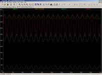
For the circuit below (not complete!) I have displayed what LTSpice is showing me the waveforms are at various points.
I was expecting to see wav-1 and wav-1-inverted to be zero-based and show a wave of approx +/- 12v. I also expected the waves for plate-1 and plate-2 to be the same, but inverted.
Is it me not understanding the circuit, or LTSpice needing some help to find it's feet?
I have a new issue, and once again I'm not sure if it's down to my misunderstanding of circuits or LTSpice.
For the circuit below (not complete!) I have displayed what LTSpice is showing me the waveforms are at various points.
I was expecting to see wav-1 and wav-1-inverted to be zero-based and show a wave of approx +/- 12v. I also expected the waves for plate-1 and plate-2 to be the same, but inverted.
Is it me not understanding the circuit, or LTSpice needing some help to find it's feet?
Attachments
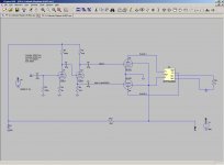
Yes, I said it wasn't complete 🙂
I wanted to see the voltages then I could take a stab at the bias - but what is shown by LTSpice is relatively useless...
I wanted to see the voltages then I could take a stab at the bias - but what is shown by LTSpice is relatively useless...
What jazbo is saying is that LT is correctly showing the result i.e. a non functional circuit because vital parameters are not set.
Try biasing just the phase splitter first (with it not connected to the 6L6's)
Try biasing just the phase splitter first (with it not connected to the 6L6's)
It took me a while to twig that even though it's connected to grid, as far as LT is concerned it's still an open circuit...
- Status
- Not open for further replies.
- Home
- Design & Build
- Software Tools
- Help with LTSpice... or something else?