Hi, Im having a go at building a low current 12v 0.4A smps. I need it to be small, and cost effective, and i hope not to have to use any ic’s.

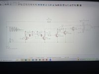
Here is my explanation of the circuit: 220v DC flows in via J1. This 220v is then stepped down by the resistor divider, to under 50v. This <50v powers the switching circuitry
(this low current 50v is just supplying the switching circuitry, it is NOT connected to the output). The switching circuitry switches 220vdc through isolated transformer T1.
Finally, the one and only output of this SMPS on pins 1 & 2 of t1, is completely isolated from the 220v input.
My issue is that Q5 isn't switching, i believe the astable multivibrator is drawing too much current from the 50v voltage divider. What can i do to supply the astable multivibrator.
I could increase the wattage handling of the voltage divider resistors, but to begin with this whole voltage divider method to supply the multivibrator is very inefficient.
I imagine everyone is scared off now.
Attachments
Last edited:
The main output is isolated? The switching circuitry is supplied with non-isolated 12v, however the switching circuitry switches the main transformer, so the main output of the smps is isolated. Take note of transformer T1

Yes, it's the control circuitry that is potentially hazardous, being directly connected to 240VDC.
But when installed inside the 240VDC supply, that will be ok.
But when installed inside the 240VDC supply, that will be ok.
Yes, that seems like a good idea. Will implement in the morning. The transistor astable multivibrator is switching at 10khz though, so the reservoir capacitor might not have enough time to charge up between pulses.
This is a very bad design. Leave designing AC line switching power supplies to someone else...
The dumps and closets around the world are full of trillions of 12 volt power supplies. Every home wireless router has one...
The dumps and closets around the world are full of trillions of 12 volt power supplies. Every home wireless router has one...
Yes, that seems like a good idea. Will implement in the morning. The transistor astable multivibrator is switching at 10khz though, so the reservoir capacitor might not have enough time to charge up between pulses.
You just make the capacitor large enough to store enough charge to support the voltage under the load.
I think a few uF would be adequate, and would also function as a soft-start.
R13 is given as 150k, which is not going to work as it limits the maximum output power to 0.2W, rather than the required 5W.
The switching element in a SMPS would normally be a MOSFET or IGBT, not a BJT. Why not use a zener to set the driver circuit supply?
You won't get good regulation with such a design as there is no opto-coupler feedback from load to driver side.
Anyway why not just use a standard mains SMPS unit - they work just as well from DC as from AC as the input is a bridge rectifier. Something like this: https://www.switchelectronics.co.uk...rzCz5wasELWUzxVLEgPKHcmlrCfniG0CbitaGbJNNHID3
The switching element in a SMPS would normally be a MOSFET or IGBT, not a BJT. Why not use a zener to set the driver circuit supply?
You won't get good regulation with such a design as there is no opto-coupler feedback from load to driver side.
Better to use an IC... Otherwise it won't be small and cost effective(!). The datasheet application sections are a valuable resource.I need it to be small, and cost effective, and i hope not to have to use any ic’s.
Anyway why not just use a standard mains SMPS unit - they work just as well from DC as from AC as the input is a bridge rectifier. Something like this: https://www.switchelectronics.co.uk...rzCz5wasELWUzxVLEgPKHcmlrCfniG0CbitaGbJNNHID3
This is a very bad design. Leave designing AC line switching power supplies to someone else...
The dumps and closets around the world are full of trillions of 12 volt power supplies. Every home wireless router has one..
Good thing its a personal design then, that Im doing as a personal project, to learn. Its going to be used inside an amplifier SMPS, to provide auxiliary supply for a tl494.
Because of that, it only needs to supply minimal current, and does not need to be isolated. Perhaps try to contribute something useful, instead of just suggesting to let others do it.
Yes, i might have a look into the tny26x range of ic’s if i have too, they are often used in mobile phone charger bricks to supply 5v from 220vac.R13 is given as 150k, which is not going to work as it limits the maximum output power to 0.2W, rather than the required 5W.
The switching element in a SMPS would normally be a MOSFET or IGBT, not a BJT. Why not use a zener to set the driver circuit supply?
You won't get good regulation with such a design as there is no opto-coupler feedback from load to driver side.
Better to use an IC... Otherwise it won't be small and cost effective(!). The datasheet application sections are a valuable resource.
Anyway why not just use a standard mains SMPS unit - they work just as well from DC as from AC as the input is a bridge rectifier. Something like this: https://www.switchelectronics.co.uk...rzCz5wasELWUzxVLEgPKHcmlrCfniG0CbitaGbJNNHID3
I could use an smps unit, however that takes a bit of the fun out of it. I have designed and made large high current dc-dc smps before for car amps, but this is my first small ac-dc supply. Have to start somewhere.
The output of this little smps does not need to be regulated, as its going to be inside a larger smps, supplying the larger smps’s switching circuitry (i know, it sounds odd) put simply, its a small auxillary smps inside a big smps, as i want to avoid using auxillary windings on my big smps, as it makes startup design a little harder.
Bjt should be fine for switching such a small transformer, though my bad, i completely forgot to note that transistor “npn” is a mje13003 transistor
to avoid confusion ill give the two different smps’s two different names: SMPS 1 is a large smps thats going to be using a half bridge to output +\-60v. And SMPS 2 is a very small smps that is just used to supply SMPS 1’s switching circuitry, specifically a tl494 hooked up to a GDT.
Smps 2 could be used to supply smps 1s switching circuitry just for a few seconds at startup, then once smps 1 is going, i could use an auxillary winding on smps 1s transformer, so that it can shut down smps 2 and just supply its own switching circuitry.
So i just need to get smps 2 to be able to supply smps 1s switching circuitry for a few seconds or less, at startup, irregardless of how horribly inefficient smps 2 might be.
You could use the complementary output of the astable to drive the other end of the transformer winding like in a full-bridge SMPS, but through a small capacitor to prevent core walking. That way the transformer would also be smaller (no stored energy) and the output well-behaved.
Added in a small 4.7uf resoirvoir cap on the <50v line, which made the square wave output on q4's collector look a little nicer, however as soon as q5 is added in, the square wave on q4's collector is clamped down, regardless of whether there is a load on q5.
Q2's collector is still putting out a square wave, however past R10, its clamped.
Q2's collector is still putting out a square wave, however past R10, its clamped.
Last edited:
the square wave on Q5's base is peaking at about 0.7v, which might be just enough to switch it. Gave it a test run, with r13 changed to 50k, to allow more current through t1. It actually worked, outputing 28vac on the seconary of the transformer 🙂 . voltage divider for switching cicuitry started to get fairly warm, so i will take marks advice and use a zener across a smaller voltage divider.
Currently revising it to work like a half bridge, as newvirus suggested.
Currently revising it to work like a half bridge, as newvirus suggested.
Last edited:
- Home
- Design & Build
- Electronic Design
- Help with low current 12V SMPS design