Hello I just purchased a used Valhalla power supply for a DIY project. I like the idea of it. anyway I plugged it in and no motor spin, no LED on the switch.
I went through the basic trouble shooting ensuring I had 300v DC of C1 and the usual suspect of resistors read the correct value. I was about to move onto the some of the smaller electrolytics but before doing so I checked the switch ( the seller didnt originally give me the switch but did today when picking up another part.
The switch and the ribbon cable stay open circuit when pressed. All 3 connections to each other. I therefore think the switch is broken ( it can happen )
Can anyone guide me what pins to short out on the board to test this theory and see if the motor spins up? i think shorting pin 4 & 5 should do what I want but i would like to check.
Thanks
Chris
Attachments
Looking at the circuit you posted and the switch could be a momentarily action type only closing while pressed. With PSU disconnected from the mains do you read a short across pins 3/4 and 5/6 when you press and hold the switch in.
Without seeing the full diagram its impossible to advise further.
Without seeing the full diagram its impossible to advise further.
Thank you for the fast response, very much appreciated.
The full diagram can be viewed here ( https://www.audioservicemanuals.com/l/linn/linn-valhalla/3547850-linn-valhalla-schematic )
With my continuity meter I cant get even momentry continuity. Let me go and re check. the meter isnt great but should be capable of reading a quick connection.
Thanks
Chris
post #33 under
https://www.diyaudio.com/community/threads/two-speed-valhalla.97740/page-2
and post 16 under
https://www.diyaudio.com/community/threads/linn-lingo-schematic.297346/
so as post #35 under
https://www.diyaudio.com/community/threads/linn-sondek-diy-mods-that-work.272570/page-2
show the circuit diagram
great issue in the meantime are the fact, that there are a lot of threads to the same topic.
With my continuity meter I cant get even momentry continuity. Let me go and re check. the meter isnt great but should be capable of reading a quick connection.
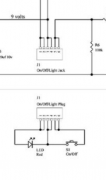
So looking at the diagram and another check would be to measure the voltage across R6 which should be zero. When the button is pressed (and held) it should go to 9 volts.
Is the +9 volt supply correct?
Hi - sorry for the slow reply - I had to get a new meeter.
I get 9v on the board but pressing the button does nothing.
Checking for continuity on the switch gives me nothing - eg press the switch ( when removed from the board ) gives no continuity between any of the pads on the ribbon cable or the switch itself.
I think if I connect the centre pins to the correct outer pin I should get see if the motor will start. If I pick the wrong outer pin ( the one that goes to the LED ) I am not sure what damage i can cause. Its a 5050 bet for me........