I've searched the forum for over an hour....I'm sure the answer to this question exists, but I can't find it.....
I have an LCD panel with two connectors: a 15 pin connector with 14 wires in it and a 14 pin connector with 12 wires in it. The wires are mostly blue, but there aer some green black red and yellow. I've read about building your own VGA cable, but can't find a diagram to use....anybody got one or know where to look?
Thanks!
Attachments
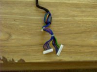
What model of LCD panel are you using? I have an InFocus that I could use to determine the correct pinout for, but I don't know that it would match your panel. Judging by the cables in the image, I'd guess that you have a Sharp panel. Let me know and I'll do my best.
Thanks for the help! The panel came off of an older model Zeos laptop. They got bought out a few years ago by another company. I contacted the company, but they don't have that detailed info on the older models. I'm hoping that there was a standard pinout...the sharp model maybe?
I didn't realize that was an LCD module - I thought it was a projection panel. If you have a multimeter, then you may be able to get a reading for the power input leads by using the laptop the screen came from, but other than that I'm not sure what to think about it. You may also look around at LCD controllers to see if you can find one that uses the LCD connectors that your LCD has. There are several "common" types of connectors, but I don't have enough experience with this sort of thing to be able to tell you what kind you have. Sorry I can't be of more help.
- Status
- Not open for further replies.