Hello,
I also have a Kelvin Labs integrated with similar problems to those listed above. It also had an issue with the rectifier diodes which I have replaced but there is still an audible buzz through the speakers. I have also replaced all the electrolytics on the main board.
On power up there is a delay, then the relays click in and then the noise is audible through the speakers. It is mostly independent of volume setting but increases slightly towards full volume. I have disconnected power to the phono / pre-amp section. Input selection makes no difference and it is on both channels.
My version doesn't have germanium transistors but ztx450/ztx550 and bdv66a/bdv67a.
I am not sure what to check for next, how did others in this thread cure the problem?
I never got mine working properly (without noise), life got in the way and my depression is not helping...
Try with ceramic or polyester capacitor across the main rectifiers and or replace them with something with higher recovery times.
I know it is probably not the best advice but it's a start, the power supply always benefits with some improvement to reduce ripple/noise.
Good luck
Try with ceramic or polyester capacitor across the main rectifiers and or replace them with something with higher recovery times.
I know it is probably not the best advice but it's a start, the power supply always benefits with some improvement to reduce ripple/noise.
Good luck
Apologies for not replying sooner and also sorry to hear that you are living with the hum. I had hoped to reply within a few days with the solution but it took a long time and a couple of component orders to find a fix.
I suspect that we all have had the same issue in the relay driver section caused by the initial rectifier diode fault. Referring back to the circuit drawing the transistor in mine was a ZTX450 and I suspect this was faulty, possibly along with the diodes. Initially I replaced the flyback diode, the diode by the resistor along with the zener but I was going around in circles with it working, switching off, then it failing with noise again and finally with relays not always closing.
I replaced the relays on mine with Omron G6S-2-Y DC12, the zener is a BZX85C12. The other diodes I think are 1N4148. I removed the 4th pair of legs on the relays in order for them to fit and linked the circuit from below on one channel to match the old relay's pin out placement.

Did yours have the 1uf stacked foil input caps on the underside of the board? I do not know if these are original or not.
Mine has been altered at some point with 100uf 50v bipolar caps in the feedback position. I've replaced these with tants as this looks like what the originals had. Do you know if that value is correct? Mine had quite a lot of residual hum after the above fix but replacing these with polars seems to have lowered this somewhat.
I replaced the main rectifier diodes with BY500-400 and I am tempted to increase the supply caps to 15000uf to see if this lowers the residual hum further before fitting it all back together.
I suspect that we all have had the same issue in the relay driver section caused by the initial rectifier diode fault. Referring back to the circuit drawing the transistor in mine was a ZTX450 and I suspect this was faulty, possibly along with the diodes. Initially I replaced the flyback diode, the diode by the resistor along with the zener but I was going around in circles with it working, switching off, then it failing with noise again and finally with relays not always closing.
I replaced the relays on mine with Omron G6S-2-Y DC12, the zener is a BZX85C12. The other diodes I think are 1N4148. I removed the 4th pair of legs on the relays in order for them to fit and linked the circuit from below on one channel to match the old relay's pin out placement.
Did yours have the 1uf stacked foil input caps on the underside of the board? I do not know if these are original or not.
Mine has been altered at some point with 100uf 50v bipolar caps in the feedback position. I've replaced these with tants as this looks like what the originals had. Do you know if that value is correct? Mine had quite a lot of residual hum after the above fix but replacing these with polars seems to have lowered this somewhat.
I replaced the main rectifier diodes with BY500-400 and I am tempted to increase the supply caps to 15000uf to see if this lowers the residual hum further before fitting it all back together.
Last edited:
The last part of the puzzle on my amp is the balance pot resistors. It seems that someone has removed them prior to me getting the amp and the lack of them is the reason for the increased residual hum.
Do you happen to know their value?

Do you happen to know their value?
My original fault and cause of hum was the voltage regulator for the preamp in the back.
1st: don't remember seen those 2 capacitors on the cooper side of the board and 2nd looking at your volume/balance board it doesn't seen to be anything missing.
I just came back from holyday of hell and need a couple of days to cool off but I will have a look at my amp during this week and take some pictures.
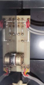
Thanks, that image is cropped from an image posted upthread. My volume & balance board is missing those two capacitors. The balance pot is broken on mine so i am going to have to replace it. It would be good to know the original values of resistors although it is not really important for the functionality of the circuit.
So let us start...
Have a little play this afternoon and found a few things
To start the heatsink is hotter on the right side so will have to investigate the bias.
The volume board you posted is different from mine for a start ( earlier version? ) mine is marked with OL 89 at the centre and 49 23 by the balance pot.
The Volume pot is a cheap stereo Alps 10K and the 2 resistors are at the bottom side of the board and are 150K 1% 1/4W.
Going to start taking it apart to get access to the cooper side of the board to check for those capacitor and replace the Germanium transistors.
Attachments

Thanks for those resistor values, that's very helpful.
Is that board on yours sensitive to EM noise? Does the balance pot buzz if touched? Mine is on the bench atm and the flying leads from the balance pot to the main amp input seem overly sensitive to airborne noise.
If I take the input directly off the lower impedance volume pot instead it seems less sensitive to noise.
I had a play with the amp this afternoon but I haven't got that far.
Replaced the rectifiers with fast recovery ones (Mur420) and planning on adding 100nf bypass capacitors to them
I did replaced the AC127/128 with a matched pair of BC transistors and after soldering them into position I realized that I made a mistake in the orientation of them(working on it)
Checking the compensation capacitor (Mylar 220pf) on my board (you have 1uf in parallel with them) I actually checked a few schematics and they range from 47pf (Cambridge Audio) to 820pf on a DIY Class A from Practical Electronics so I would say get rid of those 2 polyester caps.
About the airborne noise can't comment because I need to sort my mistake with the driver transistors before I plug it in for testing.

The last bit of remaining hum on mine was an easy fix, I'd just forgotten that I'd removed the earth to selector/tape monitor case shield when moving it about on the bench.
Those 1uf stacked caps I think are just bypassing the .47uf film input caps, so not really doing anything super useful. Have lifted a leg and tested and not anything immediately noticeable. The amp did have some questionable upgrades fitted.
Going to add an alps blue vol pot, bypass the balance and swap the feedback caps back out again for some bipolars and then call it a day with mine. I only have really small heatsinks on the bench so haven't tested longer than 20-30s yet but already sounding good!
That's good news it is always something simple that makes us scratch hour heads.
Waiting for some components to I can test mine, will let you know
Can you check the bias current on your amplifier ?
Waiting for some components to I can test mine, will let you know
Can you check the bias current on your amplifier ?
Not sure if I'm measuring correctly but I'm getting about 0.70-0.73v across each of 4 the 1R0 resistors.

Have a question for you...
Do you know or can you check the fuse rating for the 4 fuses in the board ?
Ric
Do you know or can you check the fuse rating for the 4 fuses in the board ?
Ric
Ok, so got it running with +/-8mV offset but...
After replacing the Germanium transistors with a matched set of BC550/560 I now only have 5mV flowing through the .68 ohm resistors.
Turning the pot on the board does nothing,
I haven't tried the amp with speakers yet.
Any pointers ?
Just a little edit: Lets say I swapped the BC550/560 driver transistors position around ( you know replaced the npn for the pnp) would this explain the missing bias current ?
Last edited:
Just checked the fuses, I suspect they've been replaced as part of some other 'audiophile' upgrades found in my amp. They're rated F10 250v which seems absurdly over rated, what are yours rated at?
Afraid I can't help with your other issue but if the bias current is low the pot might not have much effect...? Will photo's help with the orientation?
Afraid I can't help with your other issue but if the bias current is low the pot might not have much effect...? Will photo's help with the orientation?
Attachments

Loosing my mind with this amp, I should have left the germanium transistor in place and saved all this time I'm wasting with it...
So as I suspected I swapped the transistors positions but at least the pin out was correct (emitter to emitter/base to base and collector to collector) it would power up with all correct voltages but without any idle/bias current.
So today I fixed the transistors but now It doesn't power up (inline bulb lit up) I do measure 145mV at the 0.68 Ohm resistor but that is with the power supply measuring 1.8Vdc.
I'm going to remove the inline bulb, close my eyes and power it up strait from the 240V line (assuming a idle/bias current around 700mV it wouldn't surprise me that there is nothing wrong with the amp (was working before the trany swap))
Any suggestions ?
Attachments
- Home
- Amplifiers
- Pass Labs
- Help with Kelvin Labs Integrated