Thanks Eli. Can't say that I fully understand it all.but yes, can see the warning about the output load.
Too bad a square peg will not fit into a round peg without considerable force.reshaping.
Another thing: I take it that the .22uf 630V yellow cap from pin 2 to the Alps pot & 1M ohm 1/2W resistor is the output coupling cap? If so, would you (or anyone else) know if replacing it with say, a Miflex (or other brand) of the same capacitance (and similar voltage) make much of an audible difference or would it just be throwing money away/down the drain? (I realize coupling cap sound qualities are subjective.)
Thanks.
Sincerely,
Kingsley.
Kingsley,
I'm going to be blunt. PRR was very kind in his analysis of that circuit's flaws. It's a PoS! S/N performance is in the toilet. The device is incapable of driving many SS power amps, which, all too often, present the difficult IHF "standard" 10 Kohm load. Good design takes lowest common denominator into account.
I repeat my previous suggestions about utilizing that which is good in the "beast" and disposing of that which is bad. FWIW, the 6J5 hybrid setup will easily drive a 10 Kohm downstream load. Even a 6J5, with an unbypassed cathode resistor, may have too much gain. However, it's quite easy to add custom "padding" resistors for each of the several sources between the associated I/P jacks and the source selector switch. A small degradation of S/N performance comes with "padding", but it's TINY in comparison to the circuitry you traced out.
I'm going to be blunt. PRR was very kind in his analysis of that circuit's flaws. It's a PoS!
S/N performance is in the toilet. The device is incapable of driving many SS power amps, which, all too often, present the difficult IHF "standard" 10 Kohm load. Good design takes lowest common denominator into account.I repeat my previous suggestions about utilizing that which is good in the "beast" and disposing of that which is bad. FWIW, the 6J5 hybrid setup will easily drive a 10 Kohm downstream load. Even a 6J5, with an unbypassed cathode resistor, may have too much gain. However, it's quite easy to add custom "padding" resistors for each of the several sources between the associated I/P jacks and the source selector switch. A small degradation of S/N performance comes with "padding", but it's TINY in comparison to the circuitry you traced out.
Good Evening, Eli:
Nah, blunt is good in this case!
It is interesting that there are many (1)designer's and many (2)builder's but seems not enough of (3)both and even more so (4)those who have the experience, knowledge, and skills to pull it off with a really good product. You and PRR (and a few others) are in the 4th camp.
Thank you for offering the circuit redesign to make it better.
Guess I'll need to think and digest this one through even if the unit sounds good - at least to my ears, albeit with the incorrect output impedance to drive my Muse 100 SS amp.
Sincerely,
Kingsley.
Kingsley,
Your Muse 100 SS amp may not be an extremely difficult load. You have to check its specifications.
Employing a FET at a SS amp's I/P allows it to easily have a "friendly", high, I/P impedance. Keep the fact that FETs' electrical behavior resembles that of pentode vacuum tubes firmly in mind. Love/marriage - horse/carriage - tubes/FETs. Sorry about the non-rhyme.
Your Muse 100 SS amp may not be an extremely difficult load. You have to check its specifications.
Employing a FET at a SS amp's I/P allows it to easily have a "friendly", high, I/P impedance. Keep the fact that FETs' electrical behavior resembles that of pentode vacuum tubes firmly in mind. Love/marriage - horse/carriage - tubes/FETs.
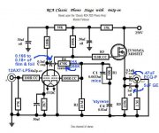
Sorry about the non-rhyme.MAJOR re-think: the volume pot goes in FRONT!! (It may already be there; otherwise this thing would be a beast, a fuzz-box.)
Slight re-thinking leads to revised NFB loop. Yes 39k in first stage cathode spoils gain but we have far more gain than we need. Raising the loop impedance reduces the original's ghastly 10k load on the poor triode. Also allows taking NFB without added blocking cap. This does (as before!) mean that the output blocking cap must be "large", but this is a show-off part.
The "Muse 100" amp is rated 51k input and I took that literally. Yes, some other amp could take its places some day. Personally I'd replace the WHOLE thing with a good pot and a TL072 which can drive ANYthing the owner puts behind it. But it would not look as pretty.
Do not trust sims! For more untrustiness I used a wrong (similar) tube and round number resistors. However the sim numbers are in line with experience. 6SL7 with similar conditions will make 20Vrms @ 5%THD, so 10V @ 2.5%. The excess gain for NFB is at least 25, so closed-loop we expect 0.1% at 10V(!) out, less at normal power amp input levels. (The Muse 100 is more sensitive than most: 0.89V.)
With CD/DAC sources this is still a lot of gain. You will never use the top half of the Volume pot. The 38k can be raised to 100k or so. (If you feel you should go to 200k, then you really don't need a preamp...)
Gv = 5.88 (15dB)
10Vrms @ 0.1% THD
2Vrms @ 0.03% THD
-1dB @ 14Hz-130KHz
Attachments
Good Evening, Eli and PRR:
You are probably correct that the Muse 100 is easier to drive.
Given that this preamp circuit is not ideal, would you be able to point me to a good-very good(/excellent) 6SN7 line stage schematic that also can utilize the 5Y3GT rectifier? It would be nice to rework the circuit as per you suggestion for 6J5 but I already have a bunch of 6SN7, 6SL7, and 5Y3GT tubes on hand that would be a shame not to be able to use them.
PRR, when you mention that the pot should be 'In front', are you referring to pot should be the first component from the RCA input and before the selector switch or right after the selector switch and not taking the output from the 3.3k, 1M, and .220uf that are soldered to pin 2? (That is, the leads of the selector switch should go to the pot and the pot going to the solder peg that is connected to where the selector switch is currently is soldered to with the 0.1uf connected to pin 4, and then the output wire soldered to the peg where the 3.3k, 1M, and .220uf that are soldered to pin 2?)
By the way, you both have been very insightful with your diagnosis and input. However, I'm not technical (nor an Electronics tech), can follow a schematic, but ask me to understand let alone explain what each part/section of a circuit does, what components values to use, how much NFB is required/to use, it beyond the scope of my abilities.
Thanks.
Sincerely,
Kingsley.
Kingsley,
The same triode is used in both the 6J5 and 6SN7, respectively single and twin. I suggested the 6J5 for heater current draw considerations. The 6SN7 draws twice as much heater current as the 6SL7 and I wanted to be absolutely sure that the heater supply, however it's configured, is not overtaxed.
Do you use phono? If so, the RCA setup can easily be adapted to use 6SL7s, instead of 12AX7s and adding 6SN7 cathode followers to buffer the O/Ps is a very good idea.
BTW, 6J5s are low cost. AES shows a 8.90 USD price per tube.
The same triode is used in both the 6J5 and 6SN7, respectively single and twin. I suggested the 6J5 for heater current draw considerations. The 6SN7 draws twice as much heater current as the 6SL7 and I wanted to be absolutely sure that the heater supply, however it's configured, is not overtaxed.
Do you use phono? If so, the RCA setup can easily be adapted to use 6SL7s, instead of 12AX7s and adding 6SN7 cathode followers to buffer the O/Ps is a very good idea.
BTW, 6J5s are low cost.
AES shows a 8.90 USD price per tube.Good Morning, Eli:
Great that you thought of the phono stage - yes, would be very nice to incorporate one. Would it require additional case work or if I'm understanding correctly, split the 6SN7 (or 6J5 if need be maybe not so much the 6SL7) in which half of the triode section for the line and half for the phono? Or are you referring to using the 6SN7 solely for the output buffer?
Still would be wonderful to have a schematic of either the line stage or the line stage & phono as a complete whole. I can then study the schematic, purchase the parts, and resolder/rewure it together.
By the way, thanks for the link to the cathode follower.
Sincerely,
Kingsley.
Kingsley,
I checked the spec's for the Muse 100 amp. Less than (sic) 1 V. of drive yields full power O/P. You don't need any line stage gain! Remember, the max. O/P of a "standard" CDP is 2 VRMS.
You build the phono preamp in its own enclosure, with its own (dedicated) power supply.
I checked the spec's for the Muse 100 amp. Less than (sic) 1 V. of drive yields full power O/P. You don't need any line stage gain! Remember, the max. O/P of a "standard" CDP is 2 VRMS.
You build the phono preamp in its own enclosure, with its own (dedicated) power supply.
Hi Eli:
Thanks for checking/finding out the input voltage spec (PRR made inference/mention of it earlier) of the Muse and that a CD/DVD can drive it without issue.
However, I do have phono/analog incorporated into the system too. I have two other tube preamps with built in phono, one SS with built in phono, and also one tube and one SS phono stage. They all work fine with the in any combo with the Muse, an Acoustat TNT-200, and even a Jolida SJ502 (with KT120 tubes) and the rest of the system.
I guess this particular pre doesn't (quite) qualify - you know how it is... was looking for a hardwired preamp and this one came along and I guess I jumped at it too quickly figuring the sound quality should be better with less traces/wiring (you know the olde principle of KISS). Well lesson learned.
Had a somewhat cheap passive at one point in time but it kind of lack the fullness of an active pre so have not gone back to it (although the LDR stuff looks/sounds(?) interesting).
Bottom line i, it would be a shame to not be able to utilize this DIY pre albeit having to rework the circuit or even replace it's internally entirely! That's why I'm here requesting assistance trying to salvage this thing-a-ma-jig.
Oh, PRR, thanks for that schematic - missed it when reading that particular post.
Thanks everyone.
Sincerely,
Kingsley.
Thanks for checking/finding out the input voltage spec (PRR made inference/mention of it earlier) of the Muse and that a CD/DVD can drive it without issue.
However, I do have phono/analog incorporated into the system too. I have two other tube preamps with built in phono, one SS with built in phono, and also one tube and one SS phono stage. They all work fine with the in any combo with the Muse, an Acoustat TNT-200, and even a Jolida SJ502 (with KT120 tubes) and the rest of the system.
I guess this particular pre doesn't (quite) qualify
- you know how it is... was looking for a hardwired preamp and this one came along and I guess I jumped at it too quickly figuring the sound quality should be better with less traces/wiring (you know the olde principle of KISS). Well lesson learned. Had a somewhat cheap passive at one point in time but it kind of lack the fullness of an active pre so have not gone back to it (although the LDR stuff looks/sounds(?) interesting).
Bottom line i, it would be a shame to not be able to utilize this DIY pre albeit having to rework the circuit or even replace it's internally entirely! That's why I'm here requesting assistance trying to salvage this thing-a-ma-jig.
Oh, PRR, thanks for that schematic
- missed it when reading that particular post.Thanks everyone.
Sincerely,
Kingsley.
Kingsley,
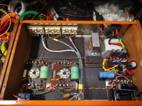
You have a nice mechanical engineering package (including case work) and some decent parts. FYI, good case work is costly. See if you can identify the power trafo and filter choke. I want to know what the capability of the power supply is or could be.
I have a "far out" concept of how to repurpose the unit and there are several Canadian members who could help you with implementing said concept.
The 6SL7 is bad for line and good for phono. So, phono is what the 6SL7s get used for. The tweaked RCA setup provided deals with the drive issue. The 50 Kohm Alps volume control (which is not junk) stays, unless you decide otherwise.
How to deal with the line section, where gain is not needed? PRR provided the answer. Opamp buffer the volume control. More than sufficient room for the additional circuitry is present between the signal tubes and the jack set. AC (cap.) coupling allows a unipolar PSU to be used with "chips" like the TL072.
Replace the SPST power switch with a DPST part. Either the opamp or the 6SL7s heaters will be energized by a "wall wart", depending on what the power trafo's capabilities are. A pair of 6SL7 heaters wired in series draw 300 mA. A 1.2 A. rated 6.3 VAC winding can provide 12 VDC/300 mA. The new toggle switch controls both the in situ power trafo and the "wall wart".
Attachments
Hi Eli:
Apologies for the late/delayed response. Not sure if these numbers/measurements will help any (as I couldn't find any markings on the power trans or the choke). Forgot to measure the resistance of the choke.
The AC Voltage measurements from the 5y3GT rectifier pins...
Pins and measured VAC
1&8=5.29
2&GND=66.5
2&4=259.7
2&6=268.8
4&GND=264.6
4&6=529
4&8=265
6&GND=264.2
6&8=264.4
8&GND=0.722
Pins 3, 5, and 7 were not connected/soldered.
Thank you the additional suggestions and the 'Far out' concept (which sounds like it would achieve the desired results).
Regarding the mentioned Canadian members who can help out, would any of them be within the Toronto (or better yet, Scarborough) area?
Currently have the unit closed and was checking out some of the other 6SL7 and 6SN7 tubes I had recently purchased. Note: During the first inspection, the trans covers on the top and bottom have been repainted and I did not see any printing on the sides/laminate.(Had used a magnifying glass to see if there were any identifying marks.) Will open it up again to inspect further trans and choke.
Thanks.
Sincerely,
Kingsley.
Sincerely,
Kingsley.
Kingsley,
Try PMing kodabmx. He lives in metro Toronto.
Those voltage measurements are of value. However, the current rating of the rectifier winding and the 6.3 VAC filament winding are what interests me. Can that 6.3 VAC winding feed either a 300 mA./12 VDC filament supply or a rail energizing a twin opamp "chip"? Also, the current handling capability of the filter choke is of interest.
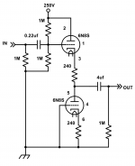
So I've been talking with Kingsley. He's coming by today.
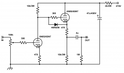
This is the schematic for what I'm thinking. I chose HER208 because I ran out of 1N4007. A conversion to CCDA, removing the current boards and sockets intact to facilitate reversion, and wire this circuit point to point on the new socket.
What do you all think?
This is the schematic for what I'm thinking. I chose HER208 because I ran out of 1N4007. A conversion to CCDA, removing the current boards and sockets intact to facilitate reversion, and wire this circuit point to point on the new socket.
What do you all think?
Attachments
So I've been talking with Kingsley. He's coming by today.
This is the schematic for what I'm thinking. I chose HER208 because I ran out of 1N4007. A conversion to CCDA, removing the current boards and sockets intact to facilitate reversion, and wire this circuit point to point on the new socket.
What do you all think?
Let me repeat some warnings. Insufficient heater current to move from 2X 6SL7s to 2X 6SN7s may be an issue. Kingsley's power amp is quite sensitive and zero line stage gain is in order.
Earlier in this thread, I proposed a hybrid version of this topology style. 2X 6J5s will not overload the 6.3 VAC filament winding, but the excessive gain and associated S/N degradation from "padding" remains a concern.
BTW, a 50 Kohm Alps control is present, but that's NBD at all.
I'm using the 50k pot. The heater supply looks up to the task, I just need to loose the 1R5 dropping resistor. Worst case, I can nix the DC and run the 6SN7 heaters on AC. As I told him, if there is too much gain, it can be reduced with a feedback loop, or a resistive divider on the input.
Power transformer still cold after 20 minutes.
Excellent!
Hi Eli & kodabmx:
Thanks, Eli for the forewarning/warning regarding the heater current and for kodabmx for making the changes and keep within the operating specs of the trans and tubes. Kudos to you both!
kodabmx and Eli, would it be wise/advisable to reduce the gain further? The original configuration/circuit was 13dB and with kodabmx' adjustments, I think it's now 10dB? Would adding the negative feedback affect the sound quality a little? If not then I'm game if kodabmx is willing to make the additional further adjustment(s). Otherwise it can left as it is currently.
Thank you.
Sincerely,
Kingsley.
Right now, 1V in will give you 9.2V out at full volume. The extra gain is nice for listening to a quiet recording loud though. I find I need to bring the control up to at least half way to clip a 20W amp.
Otherwise, if your power amp has crazy gain, I can wire it as an active loaded cathode follower instead. You end up with slightly less than unity gain.
I say come pick it up, and decide then. It will only take a few minutes to convert it.
Oh, and the volume pot is on the input side now. The previous design put the pot after the gain stage which is fine but I wouldn't do it with a *SL7 tube... Not for HI-FI anyway...
EDIT: Attached the ACF schematic.
Attachments
Last edited:
- Status
- This old topic is closed. If you want to reopen this topic, contact a moderator using the "Report Post" button.
- Home
- Amplifiers
- Tubes / Valves
- Help with Keith Kirby's DIY Tube Preamp with dual 6H9C/6SL7 and one 53YGT/5AR4.