Hey everyone, I have a couple simple questions. Firstly, I am trying to optimize a clean input stage for 5watt guitar amp which I’m converting from a newcomb ed-10c record player. I’m using half a 12ax7 and my supply voltage is 230v. Given this, what would be optimum values for plate and cathode resistors, and do you recommend using a 25uf cathode bypass capacitor? I’ve been trying to learn about load lines, but have been getting some conflicting info.
FYI my input stage goes into a 500k volume control and feeds the triode section of a 6gw8 tube. This plate runs off of the same 230v supply (the pentode section of the 6gw8 has its own b+ supply).
Second question. The amp uses a solid state rectifier that I have not encountered before. It has two diodes in series with 1 meg resistors in series with each diode. Is this a half wave rectifier?
Thanks in advance for your help!
I would use a 100k anode load and 1k8 cathode load.
The rectifier has a resistor across each diode in the belief that it will help balance the voltages across them and to use them as a bleed network when switched off to discharge the 20u capacitor.
The rectifier has a resistor across each diode in the belief that it will help balance the voltages across them and to use them as a bleed network when switched off to discharge the 20u capacitor.
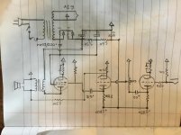
Do you know the purpose of the .022uf/600v capacitor off the front of the rectifier to the screen grid?
I’ve been trying to learn about load lines, but have been getting some conflicting info.
Hi,
I've been learning the basics of valve audio design myself lately.
If you want unabiguous information on designing/implementing loadlines, you'd do well to read Morgan Jones 'Valve Amplifiers', and - more appropriately from a guitarists perspective - Merlin Blencowes 'Designing Tube Preamps for Guitar and Bass'.
If you haven't already been there:
How to design valve guitar amplifiers
an excellent starting point.
I'm by no means an expert, but JonSnell's recommendations are more or less standard for an ECC83. The 100k anode resistor is an especially good choice, for reasons Mr Blencowe ably explains in his book. 1k2 and 820R are also common values for cathode resistors; to the best of my knowledge a lower value will give an increase in gain.
A 25uF bypass cap is also standard but, again, Merlin's book explains the reasons for selecting a different value, and the tonal implications of said choice.
The internet is a great sounding board for ideas, but I find a published text is still the best place to go if you're looking to learn*.
Matt.
* Assuming - like myself - you don't already know what you're talking about. The vast majority of contributors here do 🙂.
Last edited:
When in doubt, use 200V-400V, 12AX7, 100K, 1.5K. This WORKS.
Minor deviants like 1.8K or 120K make no huge difference. Much wider variations cause small but sometimes interesting change of sound.
Cathode cap is to-taste, depending on genre, speaker, room, and other factors. (With typical R values) 25uFd is "all the bass" (to far below guitar band). 5uFd shaves the lowest notes which sometimes boom or slap. Marshall like 0.68uFd because their customers worked with bassists and needed to shift amp power up into higher registers.
That 0.022u is probably to try to cancel the huge ripple of the low-cost half-wave supply. If the 250V and 6V secondaries are separate, I really would look at the calendar, go to a full-wave bridge, double all filter caps, and lose the 0.02.
I hope you have also installed a 3-wire cord so the chassis (and guitar jack!) are hard-grounded.
Attachments
Last edited:
Are you sure the 0.022 doesn't go to the other end of the 3.5k resistor? That would place it across the rectifiers as a snubber. And that would make a lot more sense, at least to me.
A billion old Fender amps say that the common 100k, 1.5k and 25uf choices work quite well. They are in fact right out of the RCA recommended values.
Yes, that is a half wave rectifier.
A billion old Fender amps say that the common 100k, 1.5k and 25uf choices work quite well. They are in fact right out of the RCA recommended values.
Yes, that is a half wave rectifier.
That 0.022u is probably to try to cancel the huge ripple of the low-cost half-wave supply. If the 250V and 6V secondaries are separate, I really would look at the calendar, go to a full-wave bridge, double all filter caps, and lose the 0.02.
I hope you have also installed a 3-wire cord so the chassis (and guitar jack!) are hard-grounded.
Would switching to a full wave rectifier increase supply voltage to the plates, or would it simply create less ripple in the supply voltage?
Yes, I have a 3-wire cord. Thanks 🙂
The peak is the same. The peak is what the DC supply charges up to.
The difference between full wave and half wave is the ripple is potentially larger in half wave. Your amp is single ended, so there is no hum cancellation in the power tube stage. So hum is more noticeable. But adding a CR stage to the filter can solve that.
The ripple in full wave is 120Hz, while in half wave it is 60Hz. At least for those of us on 60Hz mains.
Would switching to a full wave rectifier ...
The question is: are the HV and LV windings separate, or on a single lead as shown in the plan? If shared, there's no simple way to full-wave the HV without messing up the heater power.
No matter. You are not pinching pennies as hard as Califone did. Add an R-C filter stage. Don't worry about the DC voltage, let it be what it comes out to.
The question is: are the HV and LV windings separate, or on a single lead as shown in the plan? If shared, there's no simple way to full-wave the HV without messing up the heater power
Good point PRR. Because there is only one 6.3v tap, one HV tap and one ground /center secondary the bridge rectifier probably won’t work. Oh well, half wave will have to do.
Newcomb's own plan shows they work the power pentode 10+% over published rating. On a EL84 I would shrug- they are made new, inexpensive, and all current production reflects the gross abuse the still-popular EL84 amps dish out.
But ECL86 is only available old-stock and fetches $50-$60 a bottle!
When these tubes were cheap, and classroom recordplayers were a competitive business, Newcomb could be forgiven for their ratings-sins to get another dB of loudness without actually having enough stuff to do it easy.
I'd break into the B+ with a 470r-1K drop resistor and say 47uFd cap. 280V at the plate is not a lot less loud but gets you well on the safe side of the tube's 9Wpdiss rating. Can also lose a lot of hum/buzz, and lose the hum-null gimmick.
Newcomb's own plan shows they work the power pentode 10+% over published rating. On a EL84 I would shrug- they are made new, inexpensive, and all current production reflects the gross abuse the still-popular EL84 amps dish out
Well that raises another good point. Perhaps I’ll just use an EL84... then I can use both triodes of the 12 ax7 for the preamp. Do you foresee any problems with this idea? Like, would the EL84 be compatible with my output transformer?
- Status
- Not open for further replies.
- Home
- Live Sound
- Instruments and Amps
- Help with input stage