Yes, I couldn't figure out how to make a PCB with dimensions smaller than 25.4mm. I have very limited space.
I am looking at a YouTube tutorial right now that shows how to create a footprint. It is not limited to 25.4mm.

Thanks, I found a YouTube tutorial on how to create the footprint. I’ll start the process of creating a schematic and PCB using KiCad. Still, I am trying to understand if there’s a reason those three components (R120,R112,C145) were grouped in close proximity to each other, and/or if adding lead distance will cause issues.
Done!! I decided to use up some spare parts rather than creating a new board and buying another set of heatsinks.
Here's the board I bought from OSHPARK, and the heatsink from mouser.
I drilled a small hole through the board drain to mount the heatsink. 2.54mm header pins hold up the MOSFET, heatsink and board. The pins were bent with large pliers to create feet for soldering to original Q12/112 surface mount pads. All things considered it is a very sturdy installment. I decided to keep the gate resistor as is. I am not noticing any issues after adding 2cm of wire from the gate resistor to the gate. Now all hot spots on the amplifier main boards have been cleared out. Heat is transferring nicely to the aluminum 3mm lid and chassis. I hope to upload thermal images soon.
Attachments
Last edited:
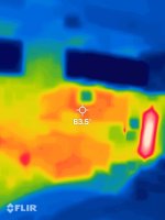
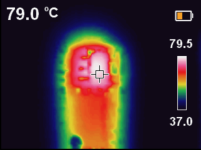
Heatsink temperatures measure around 63.5C. I estimate the die temperature around 75C after adding thermal resistance of the board and die to case thermal resistance (15C/W). Much improvement over the stock thermal management: 80C case temperature, and 90C die temperature!
Attachments
Last edited:
- Home
- Amplifiers
- Solid State
- Help with improving thermal management: moving SMT transistor above board?