
As the CM is degenerated with the 68R resistors HFE matching has some room for mismatch, as for top or bottom its up to you as this would come down to personal preference. Discreet AD797 i see?, the second post with the DB output stage gave it away 🙂 .
Colin
Colin
HOLA Y'all,
I would like to see the rest of the schematic, the front end looks interesting...
Regards, Elwood
I would like to see the rest of the schematic, the front end looks interesting...
Regards, Elwood
nelson,
That is almost the same circuit I have used. The lower transistors are probably more critical but I would replace them with similar types when you can.
How do you like the sound?
Jam
That is almost the same circuit I have used. The lower transistors are probably more critical but I would replace them with similar types when you can.
How do you like the sound?
Jam
Wow, 4t on bottom and a 3T on top..😱 . I'm about to build
something similar with 'frugalamp 2' and have simmed the hell out of it with a 3 and 4T on the bottom CM. With just a 3t
(final choice) on the bottom CM I couldn't get much unbalanced
operation with even grossly mismatched Re's. I then simmed
with different devices (for the hell of it) and by adjusting [Rj]
brought it back in balance again.
BtW like your input.. might try fet input or OPS in future..
OS
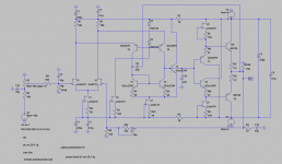
Actually it's a FET input discrete AD829 clone, but I'm also going to build a FET input AD797 like in the picture below. I'm just about to order some parts. With the "magic" transistor, it simulates almost no distortion as compared to "AD829". OTOH it simulates 100 dB OLG while "AD829" simulates 64 dB.vynuhl.addict said:Discreet AD797 i see?, the second post with the DB output stage gave it away 🙂 .
Colin
You're right, the "lower" pair is more critical. I guess it doesn't matter if there's some divergence in Hfe between the upper and the lower pair, right?jam said:nelson,
That is almost the same circuit I have used. The lower transistors are probably more critical but I would replace them with similar types when you can.
How do you like the sound?
Jam
As for the sound it fares very well compared to the original AD829 and AD797, but I'm probably biased. The choise of transistors is very critical when it comes to sound quality. With BC550/560 it's worse than the monolithic amps, but with those Sanyo's it sounds perfect to my ears - warm and full yet with all the details and authority. With Toshiba SA970/SC2240 the quality is the same, but I find it to bright. I've just found out that it sounds better with ONSemi's BD137/138 vs Sanyo SC3953/SA1538 as output transistors. I had such high hopes for the latter
 .
.Attachments
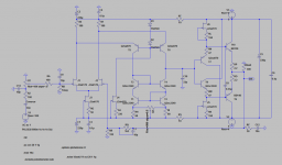
This is the FET input AD829-clone.eyoung said:HOLA Y'all,
I would like to see the rest of the schematic, the front end looks interesting...
Regards, Elwood
Attachments
What a lovely preamp. Is it class A?? At least you show schema,
unlike J. Curl 😡... will sim. Thanks..
unlike J. Curl 😡... will sim. Thanks..
Yes, it's class A driving most headphones at my listening levels. The output transistors are biased to 20 - 25 mA.ostripper said:What a lovely preamp. Is it class A?? At least you show schema,
unlike J. Curl 😡... will sim. Thanks..
I've built the AD829-clone but not the AD797-clone, yet. It runs well at higher supplies as well. Because of CCS no changes have to be made. Run at higher voltages, not having to care about voltage swing, the voltage drop to the cascode bases can be made larger. Using a 5V zener diode instead of the two 1N4148's, and corresponingly increase the 180R resistors to 1k on top of the LTP gives a slightly "cleaner"/brighter sound, and simulated it shows the distortion is reduced quite a bit. With increased supply, the emitter restors to the current mirror can be of a higher value. I think it sounds a little bit better that way.ostripper said:Have you built it , or only simmed..??
Will it run on +-12v (+- 5 is kind of low)?
"As shown in the simplified schematic (Figure 31), Node A, Node B, and Node C track the input voltage, forcing the operating points of all pairs of devices in the signal path to match."AndrewT said:post 6 schematic.
I don't understand what T1 is doing.
http://www.analog.com/static/imported-files/data_sheets/AD797.pdf
It's as used in AD797. The difference in OLG and distortion is huge using this transistor. From OLG 75 dB to 100 dB and the 2:nd order distortion is reduced from -153 dB to -200 dB at low levels. At 1V output and 300R load it's reduced from -113 dB to -135 dB.
Nelson,
In other words, it has baleful influence on the sound....It's as used in AD797. The difference in OLG and distortion is huge using this transistor. From OLG 75 dB to 100 dB and the 2:nd order distortion is reduced from -153 dB to -200 dB at low levels. At 1V output and 300R load it's reduced from -113 dB to -135 dB.
- Status
- Not open for further replies.
- Home
- Amplifiers
- Solid State
- Help with improved Wilson current mirror