Hello!
Here is my part restoration guitar project!
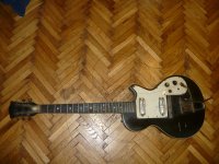
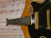
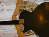
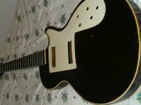
It involves a guitar left by a person left by someone that passed and has sentimental value! I cleaned the body got the new underneath components but the pickups that have to stay themselves on the guitar being, and a new set of strings will come on it aswell!
Please help, with a diagram for wiring the switches, pots, cap and pickups!
Pictures atached with progres to the moment being that we speak about it!
Thank you!
Here is my part restoration guitar project!
It involves a guitar left by a person left by someone that passed and has sentimental value! I cleaned the body got the new underneath components but the pickups that have to stay themselves on the guitar being, and a new set of strings will come on it aswell!
Please help, with a diagram for wiring the switches, pots, cap and pickups!
Pictures atached with progres to the moment being that we speak about it!
Thank you!
Attachments
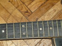
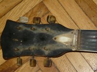
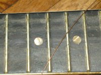
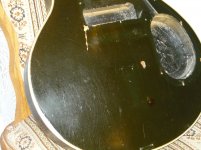
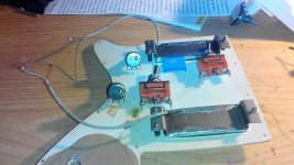
Here are some pics with it being cleaned!
Attachments
-
 P1080875.jpg757.5 KB · Views: 61
 -
 P1080876.jpg712.4 KB · Views: 67
 -
 P1080879.jpg675.2 KB · Views: 58
 -
 P1080881.jpg927.5 KB · Views: 71
 -
 P1080905.jpg667 KB · Views: 68
 -
 P1080894.jpg549.1 KB · Views: 63
 -
 P1080891.jpg641.5 KB · Views: 75
 -
 P1080889.jpg566.4 KB · Views: 64
 -
 P1080907.jpg649.1 KB · Views: 74
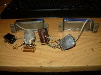
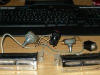
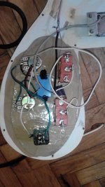
And here is what I got! There is a schematic that I found on the net, if this is the one what I have to say is that I do not undestand the switch part! mine a 2 independent switches! Thank you!
Attachments
Last edited:
The schematic shows two switches but your photo of the old wiring and components only shows one switch that I can see. I don't see any reason why the schematic would not work
 moved to Instruments and amps. oszcar this is the best forum for posts relating to instruments or instrument amplifiers.
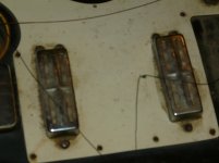
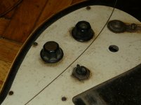
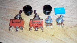
The Jack looks like it may be shot. Solder on the contact area? I'd replace that with a simple one with a metal bushing (for strength). The switches look like they were designed for very high current, and the internal contact plating may be undesirable for this use. I'd recommend switches that are specifically for guitars, or one's that have gold alloy contact plating. The switch part of the schematic looks wrong to me. With two pickups, and two switches, I would simply put a SPST switch in series with each pickup, that would feed the signals to the top of the volume control. The rest is fine. A typical tonecap size is .02uF.
If I remember correctly Fender used to have a multi way switch that allowed out of phase pickup modes as well.
Early fender guitars had a mode where teh switch was half way between modes that gave an out of phase signal as well.
Early fender guitars had a mode where teh switch was half way between modes that gave an out of phase signal as well.
The strat in between switch positions connect up two pickups in parallel, and apparently the middle pickup is wired out of phase in most cases, according to what I've read. I've rebuilt many strats so I've had a chance to see how the switch works.
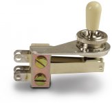
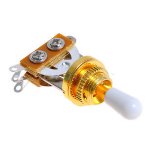
For this guitar I'd recommend an old fashioned looking Gibson switch that has the mechanism underneath mounted at a right angle, so it might fit in the cavity. The switch I'm talking about has 3 positions, the center position of which hooks up both pickups.
For this guitar I'd recommend an old fashioned looking Gibson switch that has the mechanism underneath mounted at a right angle, so it might fit in the cavity. The switch I'm talking about has 3 positions, the center position of which hooks up both pickups.
Well to answer the first question, the guitar had 2 switches but one failed, was removed and rewireing was applied.
As further it goes, it stays the same as it was before even the scratches only to be brought(the whole guitar) to a functional state with the for the moment components, till next year being a show off piece more of a kind and afterwards being redone in a more proper order!
If I could geta drawing of what I have to do further I would be very thankfull as I am not an expert in wiring guitars, so to be said for the wiring diagram i will go on the wire and solder!
Would realy love it!
I want to have each pick-up individualy on the switches so that the neck or the bridge pickup to be singed individualy! I need to use 2 switches to keep the old theme of the guitar as I have to keep the scratch plate original. So I am starting by soldering each pickup's bare wire to the middle pin of the switch and the + on the right side pin, the switches being held in the same position at the soldering time! No?!
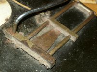
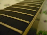
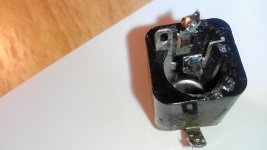
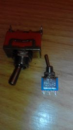
Found this little one here aswell, as you can see the neck of the switch is too small and would move into place even with washers! If I want better switches I have to buy them on demand at the radio shack cause they have only 2 models with a swing like these ones, so big! Next year I'll get 20 of them when I get some other things and I'll get them with a discount! I will get the 0.6A, 250V ones!
Attachments
Anyway:
How much soud will it be lost?
How would a final wiring schematic look like?
I want to finish it Friday night!
How much soud will it be lost?
How would a final wiring schematic look like?
I want to finish it Friday night!
I counted 5 holes on your pickup plate. If the original configuration had two switches, then you wouldn't have a place for either a tone control or separate volume controls for each pickup. I very highly recommend having a separate volume control for each pickup, a tone control for both, and a single switch to select which pickup or both, and the 5th hole is for the Jack. When both pickups are selected, adjusting the volume of each pickup will change the sound a lot, so you will have a much more flexible type of sound. The signal flow should be first to the volume controls, then the selector switch, then the tone control then the jack.
I don't know what parts are available to you in Romania, but many different companies make variations of this Gibson style switch, which looks much better than most, and is what I would use. It mounts in a 1/2 inch hole.
I don't know what parts are available to you in Romania, but many different companies make variations of this Gibson style switch, which looks much better than most, and is what I would use. It mounts in a 1/2 inch hole.
Attachments
Last edited:
I can not go to complicated on this cause is Memorabilia for my father from it's past brother. I would be glad to have it play a few notes Saturday evening in the family! Thank you all for your patience! Here is what I have got if some color lines (in paint maybe made) would depict the wiring I would apreciate it allot! here is a schema that I found but I do not see a third wire coming out of my pickup (the green wire in the shematic)! The rest would work for me in order to get them all togheder if the green wire that I don't see on my pickups is realy not intended to be present on themselves.
Attachments

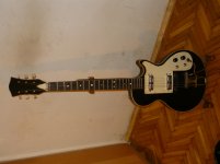
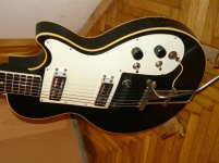
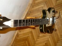
Well thank you all for your support! Herre it is done and it work very well! Thank you all once especially '' --> paulfk <-- '' for the direct answer! I gave it a try and she is done with all finished made on it! Here is how it came out, pics are atached! Thank you! Problem solved! Thread closed!
Attachments
- Status
- Not open for further replies.
- Home
- Live Sound
- Instruments and Amps
- Help with guitar pickups wiring highly wanted!