Andrew,
regarding your instructions to separate signal grounds and power grounds, and incorporate a resistor...
looking at the XO board, it would be possible to etch out sections of the ground plane to separate PS ground from signal ground.
This would be much harder on the amp boards since the ground plane is one monolithic copper trace.
Before I start modifying the XO board, let me make sure that this is indeed what you recommend.
thanks,
gary
Hi Gary,
Sorry to come late to the party 🙂 Here are my thoughts for you to consider.
I don’t think that your problem has to do with ground loops within the amplifier. I think Tom is hitting on the problem. I suspect radiation from the two large transformers. You can prove (or disprove) this by temporarily moving them out of the chassis and running a 21V twisted pair plus CT into the chassis.
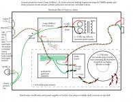
Your drawing says “pot nut and body isolated from signal ground.” The pot nut and body should be grounded to something – the chassis would be fine.
Think of your grounding architecture as eight individual ground busses. The buses need to be tied together at one point as a voltage reference but no current will flow between them. You are almost there with your latest drawing in post #20. The common system star ground is at the input of the XO. Each of the eight amplifier boards will pick up its ground buss reference through the twisted pair and the separate connection between the gainclone ground plane and the star is redundant.
Dave
Sorry to come late to the party 🙂 Here are my thoughts for you to consider.
I don’t think that your problem has to do with ground loops within the amplifier. I think Tom is hitting on the problem. I suspect radiation from the two large transformers. You can prove (or disprove) this by temporarily moving them out of the chassis and running a 21V twisted pair plus CT into the chassis.
Your drawing says “pot nut and body isolated from signal ground.” The pot nut and body should be grounded to something – the chassis would be fine.
Think of your grounding architecture as eight individual ground busses. The buses need to be tied together at one point as a voltage reference but no current will flow between them. You are almost there with your latest drawing in post #20. The common system star ground is at the input of the XO. Each of the eight amplifier boards will pick up its ground buss reference through the twisted pair and the separate connection between the gainclone ground plane and the star is redundant.
Dave
Hi David,
thanks for joining in,
so if I get you right, the star ground becomes the point of the XO I have labeled with an asterisk. The gainclone(s) and its PS is connected to ground only by the signal connection to the XO? This provides the voltage reference and "dirty ground" noise from amp PS caps etc. is shunted to ground from here before it goes through the XO?
btw, the pot itself is connected electrically to the chassis, but the signal ground going to it is isolated.
thanks, I think I am missing something (still)
gary
Attachments
Hi Gary,
You got it right on both counts.
However, those are ancillary and I believe the hum problem that you are experiencing is a result of flux leakage from the transformers.
Dave
You got it right on both counts.
However, those are ancillary and I believe the hum problem that you are experiencing is a result of flux leakage from the transformers.
Dave
while that works for signal - remember that there is a safety gnd requirement that any xfmr without double insulation must be assumed under "single fault" conditions to short pri-sec to the mains - and then must have a safety gnd path capable of handling the short current to force blowing the panel breaker
the XO board gnd isn't designed for that use - so by using the "star" in the previous drawings which can be constructed to deal with the current we just move it closer to the XO as Andrew suggested
the XO board gnd isn't designed for that use - so by using the "star" in the previous drawings which can be constructed to deal with the current we just move it closer to the XO as Andrew suggested
Ok,
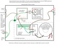
this revision addresses the current running through the XO at amp transformer fault scenario. Is this correct? What about the XO transformer? Wouldn't it too present the same problem in the case of a fault? (Of course all transformers have conservatively measured fuses in series with the active primary rail.)
I understand about the parasitic capacitance of the Xformers, to check this I will need to remove them from the chassis, (which is more involved than sketching up a drawing in Illustrator.) Should none of the wiring mods we have discussed work, this will be the next step. I was really hoping to bung all this into one chassis.
Andrew, I would still like to hear from you, if you still have the interest, as to how I might separate the signal and power grounds, or a compromise to those ends. (In this latest revision the speaker pair nearly flow together by way of a relocated star ground.)
thanks for all the help,
gary
Attachments
Last edited:
I understand about the parasitic capacitance of the Xformers, ...
Hi Gary,
I suspect that the problem is not parasitic capacitance coupling noise to the chassis. Rather, I suspect the problem is the magnetic field of the transformers inductively coupling into the wiring.
This is a hypothesis that needs to be verified or dis-proven before worrying about what to do about it. If this is the problem, there are several things that can be tried and permanently moving the transformers off the chassis would be way down the list.
Dave
Hi guys.
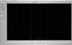
Here is some evidence to support your magnetic coupling suspicions. I disconnected all transformers but one that feeds a woofer amp, (and the XO of course.)
Attached is a capture of the 100uV or so I get across an 8 Ohm speaker. Vertical scale is in tenths of a mV, wiper is at 60 Hz of a log scale to 10k.
Attachments
proper pairing and twisting greatly reduces wiring radiated mag field, toroids are pretty low external field too - a minor tweak would be if woofer xfmrs are mounted "coaxial" then reversing the pri phase on one of each pair could reduce the pair's single turn field from simple progressive windings - a really good toriod won't have the "single turn" problem
the XO PS xmfr could radiate more mag field but it sounds like you have a pretty large case - leakage field should be inverse cube so simple air space quickly cuts it and good signal routing will keep signal-ref loop area low to reduce susceptability
with mid, tweet amps sharing a supply there is unavoidable common gnd impedance noise - possibly one of each pair should use the differential reciever hack with that amp's safety gnd passing through the other amp so the safety gnd are in series
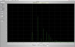
the strong 120 Hz 2nd harmonic in the noisey plot suggests common impedance coupling or radiation from large open area wire loop(s) carrying rectified PS Cap charging current pulses - it is less likely to be xfmr leakage field which should be 60Hz dominated
the XO PS xmfr could radiate more mag field but it sounds like you have a pretty large case - leakage field should be inverse cube so simple air space quickly cuts it and good signal routing will keep signal-ref loop area low to reduce susceptability
with mid, tweet amps sharing a supply there is unavoidable common gnd impedance noise - possibly one of each pair should use the differential reciever hack with that amp's safety gnd passing through the other amp so the safety gnd are in series
the strong 120 Hz 2nd harmonic in the noisey plot suggests common impedance coupling or radiation from large open area wire loop(s) carrying rectified PS Cap charging current pulses - it is less likely to be xfmr leakage field which should be 60Hz dominated
Last edited:
When measured at the mid terminals it is slightly worse and audibly much worse.
How would you interpret these measurements? I assume there could be other things that would cause this.
btw, I reconstructed the ground wiring to approximate that in post 26 with aligator leads, not tidy or perfectly twisted but as neat as possible.
gary
How would you interpret these measurements? I assume there could be other things that would cause this.
btw, I reconstructed the ground wiring to approximate that in post 26 with aligator leads, not tidy or perfectly twisted but as neat as possible.
gary
thanks JCX,
next I'll twist and organize all remaining wiring fixes. I'll check back with results.
gary
next I'll twist and organize all remaining wiring fixes. I'll check back with results.
gary
it's a pity that ground planes were adopted in your PCBs.
I am a believer in treating each circuit independently and forcing the circulating current to go where I want it to go. That way the designer remains in control.
I don't understand ground planes and as a result I cannot design ground planes. For that reason alone I do not even try to design ground planes. I do that by not using them in any of my PCBs.
I treat the signal circuit as quite separate from the speaker output circuit.
Read Leach. Similarly the power supply circuit is separate from both those circuits and the mains charging of the smoothing caps is quite separate.
Here's an update for those interested:
I have stripped everything down to bare minimum, I have just one transformer powering one pair of bridges giving +/-35Vdc to two amp boards.
All wiring is neat and twisted and the grounds reflect the final scheme in post 26.
There is absolutely no improvement in noise at the speaker, in fact now there is a healthy amount of 60 Hz to compete with the other harmonics.
I think JCX got it right from the beginning with the differential hack. When I disconnect either one of the T/M amp inputs from the XO everything quiets down. The woofer amps that have their own transformer don't behave this way, see the most recent plot attachments. So I have a quiet 2-way system if I choose what to leave out.
I guess next thing is to fit the differential mod recommended earlier.
Would someone be kind enough to explain this to me. All the amps are identical and I have an equal 8 Ohm dummy load connected to the other of the 2 amps. Both amps are referenced to XO ground next to the signals as in the schematic. Furthermore, I have constructed a stereo amp in the past using PD's boards with one 250VA tfmr and it doesn't hum. Where is the difference in impedance that causes this? The XO circuitry between T and M?
Thanks again everyone for your time and effort on my belhalf.
gary
Some reading that may help in understanding what is quite often a complex problem and a pain to solve.
Designing for Interference-free Audio System Components
A Practical Interference Free Audio System (Part 2)
Designing for Interference-free Audio System Components
A Practical Interference Free Audio System (Part 2)
Thanks marce,
Another solution, that is a bit of a retreat, is to just give each amp it's own bridge rectifier and transformer. I could fit 2 more if I mount 4 of them on their sides. This appeals to my sense of symmetry but not so much to my wallet.
JCX, in implementing the modification you posted, would that require I do that to both amps sharing the one transformer?
thanks,
gary
g
I think you only need to make one amp of each pair sharing a xfmr into a diff reciever - for instance safety gnd the tweet amp to the star and it could be driven direct single ended from the XO, same as the woofer channels
the mid amp's local "gnd" will have common impedance noise from its amp board "gnd"-Xfmr "CT"-tweet board "gnd" path's high currents
by making the mid amp into a differential reciever it should manage 30-40 dB rejection of the common gnd noise
the reason for choosing the mid amp is that the noise gain hack that keeps the chip amp stable if the XO is disconnected or off does cost some high frequency loop gain - and the mid amp sees lower frequency signals than the tweet amp
you can check 1st by just shorting the input of the amp you are modifying and connecting a 10K resistor between its gnd and the XO with the other amp wired as before
- Status
- Not open for further replies.
- Home
- Amplifiers
- Chip Amps
- help with ground scheme please