Hi all,
I've been assembling, disassembling, and reassembling my system for the better part of a year. I have rebuilt, replaced, and redesigned every stage at least once and made many modifications but have yet to be able to fix the -60dbv hum at the speaker terminals.
I put 8 of Peter Daniel's lm3775 amps into an aluminum Mac G5 tower chassis. Each powers a driver of my MTWW loudspeakers. The source is actively EQed by a LR 24dB/oct 3-way crossover, (Rod Elliott's boards and PS design.)
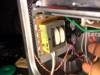
The 6 amp transformers are on the bottom and the XO +/-15V PS, each woofer amp has a 120VA CT toroid and the T/M of each channel shares a 160 VA dual secondary toroid. The rectifier boards are on this level. The amps sit on a middle shelf attached to a thick aluminum heat sink. On the top shelf is the XO. The system also has a powered remote volume and a soft start circuit, both of which have been removed for simplicity.
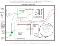
Attached is a schematic of my star ground scheme. Nearly all ground wires have be replaced by 14 gauge (from romex.) They are all individually bussed to a copper plate inches from the earth ground. (I had previously implemented a ground loop breaker circuit without success.) I have read both the Davenport and Whitlock papers that are recommended and have endeavored to problem solve by taking measurements with both an analog oscilloscope and a soft FFT analyzer on my computer. The system only is connected to a dedicated GFI (Signalscope running on my mac is not connected to this circuit but the lead grounds are.)
All individual stages measure decently well when separated; the chipamps are quiet when fed by an ipod, and the XO measures under 20uV with no source. All this goes out the window when installed inside the chassis and connected to the system star ground. I have gotten rid of some high frequency noise with small capacitors and by moving wiring around but there is a persistent 60 Hz lump which manifests harmonics, (180 and 300 Hz being the biggest at over 100mV.)
I can post pics of the amp and scope measurements if necessary. I am hoping that someone has gone through this nightmare before and can catch the thing I have missed. At this point I must either concede failure or wait for a miracle. Any advice, however trivial or patronizing, is welcome. I have also read through dozens of DIYA posts regarding this topic and tried dozens of potential fixes.
Thanks,
gary
I've been assembling, disassembling, and reassembling my system for the better part of a year. I have rebuilt, replaced, and redesigned every stage at least once and made many modifications but have yet to be able to fix the -60dbv hum at the speaker terminals.
I put 8 of Peter Daniel's lm3775 amps into an aluminum Mac G5 tower chassis. Each powers a driver of my MTWW loudspeakers. The source is actively EQed by a LR 24dB/oct 3-way crossover, (Rod Elliott's boards and PS design.)
The 6 amp transformers are on the bottom and the XO +/-15V PS, each woofer amp has a 120VA CT toroid and the T/M of each channel shares a 160 VA dual secondary toroid. The rectifier boards are on this level. The amps sit on a middle shelf attached to a thick aluminum heat sink. On the top shelf is the XO. The system also has a powered remote volume and a soft start circuit, both of which have been removed for simplicity.
Attached is a schematic of my star ground scheme. Nearly all ground wires have be replaced by 14 gauge (from romex.) They are all individually bussed to a copper plate inches from the earth ground. (I had previously implemented a ground loop breaker circuit without success.) I have read both the Davenport and Whitlock papers that are recommended and have endeavored to problem solve by taking measurements with both an analog oscilloscope and a soft FFT analyzer on my computer. The system only is connected to a dedicated GFI (Signalscope running on my mac is not connected to this circuit but the lead grounds are.)
All individual stages measure decently well when separated; the chipamps are quiet when fed by an ipod, and the XO measures under 20uV with no source. All this goes out the window when installed inside the chassis and connected to the system star ground. I have gotten rid of some high frequency noise with small capacitors and by moving wiring around but there is a persistent 60 Hz lump which manifests harmonics, (180 and 300 Hz being the biggest at over 100mV.)
I can post pics of the amp and scope measurements if necessary. I am hoping that someone has gone through this nightmare before and can catch the thing I have missed. At this point I must either concede failure or wait for a miracle. Any advice, however trivial or patronizing, is welcome. I have also read through dozens of DIYA posts regarding this topic and tried dozens of potential fixes.
Thanks,
gary
Attachments

First order of biz, read Dave Davenport's DIY Article: http://www.diyaudio.com/forums/diya...udio-component-grounding-interconnection.html
Ground from the input should go directly to the preamplifier/xo. Another connection should be made from the XO to the star ground. It would help if the RCA jack is of an insulated variety, rather than connected to the chassis.
Also, can you rotate the transformer 90 degrees on its axis?
Ground from the input should go directly to the preamplifier/xo. Another connection should be made from the XO to the star ground. It would help if the RCA jack is of an insulated variety, rather than connected to the chassis.
Also, can you rotate the transformer 90 degrees on its axis?
Hi Jack,
Thanks for your reply, I remember you helping me out in the past.
I have had trouble negotiating some of the info I have come across. For instance, the Whitlock paper shows a diagram of the input grounds going directly to the star ground. The differences are clearly due to my lack of understanding. I have tried it both ways without success. I have also removed the pot and selector and run straight to the XO. I'll reconfigure it the way you suggest. Help me understand this, I am under the impression that we want to reference the signal at every new stage to the same star ground point, without creating a loop at any point. The crossover then is the first stage, not the input jacks and pot?
I mounted all the inputs on a 3/16" ABS plastic board to insulate them from the chassis.
The XO power supply (shown) has moved around the chassis. You can see it is mounted on a protoboard with the rest of the PS components. It has been next to the XO, on the other side of the chassis next to the power in, out of the chassis on the desktop, and on top of the chassis. None of these positions seems to have made a difference. Currently it is isolated from the chassis, mounted on a plastic tray (a former divider inside the computer) and has it's ground soldered at the point to point wiring where the filter cap grounds meet.
What's next?
gary
Attachments
In my design, the diode board is connected to the star ground as well as the center-tap of the transformer, and the amplifier board only connects to the ground from the diode board. The center-tap of the transformer does not connect directly to the diode board.
Hi Tyler,
I used the arrangement you mention at one point, (transformer CT, rectifier boards, and amp boards connected individually to the star ground.) I didn't notice a significant difference. Although this was on the bench.
I connected the transformer-diode board-amp board grounds in series after reading the Whitlock paper on grounding in which (as I understand it) he recommends a star of star formation or, at least, keeping the stage and its power supply grounds connected before going to the star ground. There's a section on the merits of a ground buss that illustrates this.
Here's the paper:
www.jensen-transformers.com/an/generic seminar.pdf
Please set me straight if I am drawing incorrect conclusions.
gary
Hi,
I have not read the other Members advice, but I would like to take you back to your post1 layout.
There is an input arriving at the RCA socket. This is a two wire circuit. It must have a flow from the source and a return back to the source.
You have a red connection from RCA to Selector and a red connection from Selector to Attenuator. These red "flow" connections each need a return.
A pair of flow and return wires must carry the signal through the various routes between stages and in stages.
The attenuator already has a two wire circuit to the XO PCB.
The three connections, from RCA to Selector to Attenuator to XO, should all be twisted pairs.
Now we have the input side with all the correct flow and returns.
Look at your two input grounds.
RCA to Star and XO to Star. These are returns/voltage references, where are the complementary flow? Ahh, maybe better for the time being to think of one of these as a voltage reference, later when you understand all the flows and returns, you might be able to identify the flow that complements this return.
Delete one of these grounding links. It will need you to experiment to decide which is better for your inputs. Either the RCA to Star or XO to Star will perform, but one is likely to be better than the other.
Last edited:
Hi Andrew,
thanks for your reply.
In reference to your first instructions: You are suggesting that I need a 4-pole selector switch so L in, R in, L shield/ground, and R shield/ground (from one of the three input pairs) all are switched at one time? I am using a selector that has no dedicated ground lug and is a 2P5T type. Or does this simply mean that the input ground/shield should "accompany" the signal to the selector but not actually land on it?
In regards to the second piece, I will reconfigure the drawing with the 2 possibilities you suggest to make sure I have it right. I'll do that tonight.
Thanks,
gary
effectively you are asking if the selector must switch the ground.
I would say no.
You must include the route of the returns with the flows for each input circuit.
They will all end up having a common star either at the selector switch or at the Group of input RCA's. That's introduced a third option for where the input reference ties in to the star ground.
I would say no.
You must include the route of the returns with the flows for each input circuit.
They will all end up having a common star either at the selector switch or at the Group of input RCA's. That's introduced a third option for where the input reference ties in to the star ground.
sometimes these remote/armchair suggestions work out??
can I be the 3rd to recommend Not connecting signal input gnd to chassis "star" directly?
all input paths (sig and sig_gnd) should 1st go to the XO board
your diagram doesn't show a XO PS gnd to XO gnd wire? - it is needed, twist all 3 XO PS wires
a XO board gnd then goes to the chassis star
I would connect each amp board to each diode board, xfmr ct with equal length twisted pairs (V+, PG+) and (V-, PG-) on Peter’s rev B board - possibly entering the amp PCB from the opposite side of the board from the signal wiring
twist each speaker output and load gnd return - I hope all output terminals are isolated from the chassis? - your illustrated shield on the output likely does nothing useful
for safety you need a gnd path from each xfmr secondary (when not using double insulated xmfr) to the chassis/safety gnd, taking the safety gnd connections from (through) each amp board could be OK if all of the connections are secure, heavy enough
the "Nuclear Option" for internal signal connections is to make each amp a differential receiver - not hard - only a few added components per amp board
for stability I would use noise gain compensation since the chip amps aren't unity gain stable - so in addition to the usual 4 resistor differential amp with gain there would be a series R1,C1 between the chip amp's +,- inputs and a cap C2 to local amp gnd to AC gnd the + amp input
lifting Ri and adding R2 gives a differential input – but not balanced input impedance – which could be OK as long as we only need to reject V in the dirty gnds – which is the case if stray magnetic field is reduced by twisting high current wires and by twisting the XO out signals and gnds
the 100 Ohm output series R on the XO buffers should be shorted or a matching 100 Ohms added in each XO output signal pair's gnd
the low frequency common mode rejection is limited by the ratio match of the signal input and feedback dividers
Attachments

Last edited:
Thank you both for your replies,
it would seem I have my work cut out for me. Truthfully, none of the amps' B+ and B- have twisted wiring, some even have slightly different length wiring given the uncentered relationship between the diode boards and the amp boards. I noticed in PD's instructional few wires are twisted, maybe this is because they are so short.
I'd like to implement changes one at a time to check for improvements methodically. JCX, I appreciate the "nuclear option" and will enthusiastically give it the go should the input and XO improvements come up short. (Figuratively speaking that is.) I have tested each of the chip amps and they perform very well when connected to a test source without the XO and inputs. In fact the whole system sounds absolutely fantastic but for the hum in between songs.
Please see the attached revision of the ground scheme, I trust I have adequately interpreted the advice given. I have had it drummed into my head that a star ground is the only and best solution and would ideally have each component tied to star ground, the idea that the PS for each stage should not go directly to star ground but append to its circuit seems to waver from this logic.
First things first. Please look at the attached illustration input/XO section and confirm it accurately reflects your comments.
thanks,
gary
Attachments
As both AndrewT and jcx hinted at and gave some solutions for, there is another way to get hum, besides not having good star grounding and causing sensitive ground returns to share a conductor with larger hum-frequency ground-return currents:
Hum can also easily be induced by AC fields in the air. It can happen when a signal conductor or path and its ground-return conductor or path do not stay close-enough together, over their entire length, which in the case of the inputs is everywhere between the input jack and the resistor that goes from the chipamp's input pin to ground (not to mention the input cables). (It works that way for all other conductor pairs, too. But let's focus on the signal input pair, first.)
If there were no intermediate connections, probably the best practical way to stop it from happening would be to have the signal conductor and its ground-return conductor twisted tightly together, inside of a shielded cable, with the shield tied to chassis or star ground at the input jack end only. NOTE that the shield is NOT the signal ground conductor, and is not connected to it. i.e. It would be a shielded twisted-pair cable.
At each end, where the conductors must be separated for connections, the separation should be absolutely minimal, with the twisting going right up to the non-ground end of the input resistor, for example, and the ground return wire right against the resistor body while going to its ground end. (And if you don't have shielded twisted-pair cable, at least twist the signal and signal-ground wires tightly together.)
All other "natural pairs" of conductors should also stay as close as possible to each other, everywhere. Twist them all tightly together, over as much of their length as possible.
The underlying principle is expressed by what is often called Faraday's Law. Any loop of conductor will have a time-varying (in this case AC) current induced in it when the loop is in the presence of a time-varying magnetic field (which includes an AC electromagnetic field). Such currents will then induce a voltage across any impedance in the loop. In the case of the input signal/ground pair, the hum voltage would be induced right where you don't want it, across the power amplifier's input.
It also works the other way around. i.e. An AC current in a loop will induce an AC field in the air.
The solution is to minimize the "loop area" formed by each and every conductor pair (but especially the signal-level "receiver" pairs and the AC [and rectified AC] "transmitter" pairs).
So twist everything tightly together, including all AC pairs, and all DC supply-and-return pairs, and output pairs, etc.
Also physically keep separated, as much as possible, AC and high-current conductors and devices from each other and especially from low-current and signal-level conductors and devices. If such conductors must get anywhere near each other, they should be running perpendicular to each other.
Sometimes at least, if the main problem really is too much separation (and resulting "loop area") between the signal input and its ground conductor, then the hum will be worse when a source (tested without a signal) or a shorting plug is connected across the input than it is when nothing is connected. So you might want to try that simple test.
If you haven't considered all of this, at least it's something else to try.
Cheers,
Tom
Last edited:
Thanks Tom,
so keeping signal and ground wiring as short as practical should never sacrifice keeping them equal in length and tightly twisted. And the loop you are referring to is not an electrical ground loop, but a physical open space between a signal and ground pair.
I will start applying this to all offending cases.
I have discovered that wiring is a mysterious business; I have tried to keep power wiring away from signal wiring, crossing perpendicularly, putting power wiring up against the chassis, shielding when appropriate and several other techniques, but if I poke my finger in one of several spots, without touching any wiring or even coming close, my noise signal will increase dramatically, sometimes exponentially.
I wonder if I should have used multiple chassis? I just love the idea of one box, one on switch, one knob and all this great sound comes out.
cheers,
gary
overall better looking,
could add details of dual gnd twisting w/xfmr-to-diode V_AC+,- and diode-to-amp V_DC+,-
you are fighting 2 sources of noise:
radiated mag field coupling from PS and Load high current loops to signal, reference loops - per Tom's comments above
properly pairing high current loop wires, twisting reduces physical loop area and radiated magnetic field from PS Cap charging pulses or load drive/return (and alternating field direction from adjacent loops in the twisted pair causes field cancellation at distances greater than the twist pitch)
and twisted signal, reference pairs have reduced coupling to external mag fields for the same reasons
common impedance in "gnd" carrying high currents and signal using the same "gnd" path as reference with the high current causing series V drop
the amp, XO to star gnds should only carry pri-sec capacitive leakage current which should be very small at low frequencies
the large PS Cap charging current pulses from the xfmr secondaries, rectifiers is confined to "dirty gnds" between xfmr secs and amp boards
Last edited:
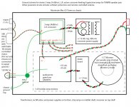
looking very much better.
A few suggestions.
The mains input earth wire is shown going to Star Ground.
Instead take it to a permanent chassis lug adjacent to the mains input socket.
Move the Star Ground to the centroid of all the Audio connectors that use it.
i.e. move it up and to the right.
Show two separate ground links from each PCB to Star Ground. Each PCB should separate Power Ground from Signal Ground.
The ground link from XO PSU to XO should be moved. The XO PSU connects with a twisted triplet to the +ve, -ve and Power Ground. That Power Ground links to Star Ground. The XO has an input pair. The return is the Signal Ground, that goes to the Star Ground.
Treat each of the Power Amps exactly the same, Power triplet, Power Ground, Signal Ground.
The Speaker Return is shown stopping on the Power Amp PCB. No, it should follow the route of main current flow across the PCB and then go to the Star Ground. Only return the Speaker Ground to a monoblock PCB where the Audio Star Ground can be on the PCB. This cannot be done with a multichannel amplifier, even when multiple transformers are used (dual mono).
Finally the long wires to Star Ground do not have zero impedance, they have capacitance to chassis and other wires, they have resistance and they have inductance. The help minimise the effect of these complex impedances each PCB that has a dual Ground (Signal & Power) can use a low value resistor on board to connect the two separated grounds. Use anywhere between 1r0 and 100r. This route should be very short to avoid the same problems that the long lines to Star Ground inherently have. Remember I said move Star Ground to centroid. This was to minimise the impedances on each of the connections. Include Speaker Return in this group.
From the above, a compact layout should perform better than a widely spread out version.
Last edited:
Silly question maybe, but have you checked continuity on all ground connections? As in probe ground signals on each board to each other, to make sure the wires are all connected well. Just something I thought of when you said proximity of your hand causes a change in the noise.
Great stuff, thanks for all the help.
Tyler first since his point is quickest: I have checked continuity. This is not a silly question and could be (and in my case before, has been) the simplest, most likely and indeed, the problem. I wish it was the case now. The noise I get by putting my hand into the chassis occurs when I come close to the DC line from XO PS to XO. In an attempt to separate the transformer and it's magnetic currents from the signal I put it on the bottom with the other toroids, and XO on top. This has made for a 16" connection between the two. When that wire is not in just the right place, the noise on my scope jumps between 10dBv.
Andrew. I have some confusion with several of your points:
"Show two separate ground links from each PCB to Star Ground. Each PCB should separate Power Ground from Signal Ground."
As I'm sure you know, Peter Daniel's design incorporates 1 comprehensive ground plane on the amp PCB that is shared by V+ ground, V- ground, and signal ground. This ground has solder points next to each respective voltage point but there is near perfect continuity between all three. I assumed that this design was intended to make the amp pcb itself a star ground of sorts. Clearly I am not yet fully understanding your lesson on "flow." Can I run more than one ground FROM the amp PCB without creating a ground loop?
The XO boards I am using (Rod Elliott's,) have a bisected circumnavigating ground plane (if that makes sense,) so once again signal and power share this one ground track. Once again, how should I separate these grounds when they are mutual on the board? This brings up another question: How do I have a signal/ground pair flow from the XO to the amp board without that creating a ground loop back to the star?
Please take a deep breath and bear with me. I understand that you and others have dedicated no small amount of time to helping me. I really appreciate it. I am confident that once I understand the message here I will implement it correctly. (I have had mixed results in the past with blindly following instructions.)
I will re-read the posts and revise the schematic,
thanks everyone!
I agree with Andrew's 1st 2 points
after that I'm not sure we're looking at the problem the same way - too many cooks? or valuable alternative viewpoint?
my reasoning is that there is "dirty gnd" carrying ~10? A PS Cap charging current peaks and several A of speaker load current between each xmfr and diode/amp boards - but since each branch is isolated by each xfmr the high current loops all complete localy in the PS Caps, amp chip and load wiring
the only current flowing in the "safety" gnd from each amp board to the "star" is the xfmr pri-sec capacitive leakage current ~ mA
the story above should work really well for woofer channels with each amp having its own xfmr isolated PS
if you have 2 amps like your mid/tweeter amps connected to the same PS xfmr secondary there will be a common impedance caused difference between the signal gnd of each
so before going further - do you have dual CT secondaries (or just use half wave rect) and therefore have galvanic isolation between mid and tweet amp PS?
or do you use the mid/tweet PS xfmr dual sec as a single CT xfmr with a hard wired connection between each PS?
Last edited:
Hi JCX,
The mid/tweeter PSs are as follows:
Dual secondaries from transformer, no CT. Each secondary goes to a bridge rectifier. Rectifier board has output nodes for dual V+, V+G, V-, V-G. These go to 1 each of tweeter amp and mid amp. The other channel is the same. If I remember correctly, PD recommended that I share the one rectified supply between the two amps when using a single transformer, (as opposed to 1 tranny supplying 2 rectifiers each supplying an amp.) Anyway, this reflects the second of your two scenarios.
Note that this arrangement is different to the woofer amps. They each have one CT transformer supplying a single bridge rectifier. This reflects the first of your two scenarios.
I hope this answers your question adequately.
Also attached is a revised ground scheme attending to some of Andrew's comments.
thanks,
gary
Attachments

Last edited:
- Status
- Not open for further replies.
- Home
- Amplifiers
- Chip Amps
- help with ground scheme please